Siemens Industry, Inc. 38 A6V12198161_en--_a
Smart Infrastructure
9. CONFIGURING THE SWITCH IN LEGACY NCC APPLICATIONS
This section briefly describes special programming considerations for the NCC associated with the
Ethernet fiber switches. Refer to the NCC Manual, P/N 315-049679, for more detailed information.
There are a maximum of four NCCs in the entire complex.
• Example of IP address range is 192.168.1.1 – 192.168.1.64
• XNET Address Node ID range is 1-64
• NCC database requires Node IDs from all nodes in all XLS, Desigo Fire Safety Modular,
or Cerberus PRO systems
• NCC requires Node IDs and IP address information from:
- NCC
- Fiber Optic Switch
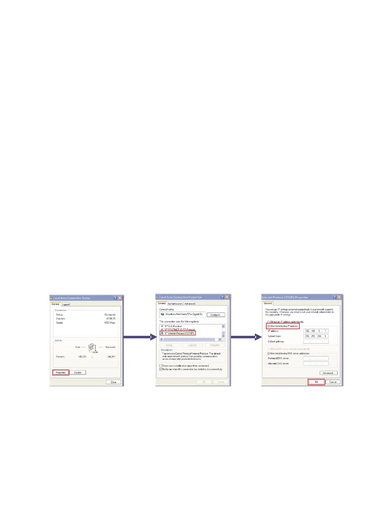
9.1 Initial Setup
To setup the IP address of the NCC, execute the following steps:
From the desktop, click Start > Network Connections > Local Area Connection.
From the Local Area Connections Status window, click Properties.
From Local Area Connections Properties window, click Internet Protocol, then Properties.
From the Internet Protocol Properties window, choose Use the following IP address and
choose an IP address in the range 192.168.1.60 - 192.168.1.63 with the subnet mask of
255.255.255.0.
Figure 9–1: IP Address Setup
• Configure Windows XP, Windows 7, or Windows 10 on NCC machine with Firewall set to
OFF.
• Set up the SNMP protocol as follows:
 Loading...