Data library
8.7 Formats
3WL/3VL circuit breakers with communication capability - PROFIBUS
266 System Manual, 03/2011, A5E01051353-02
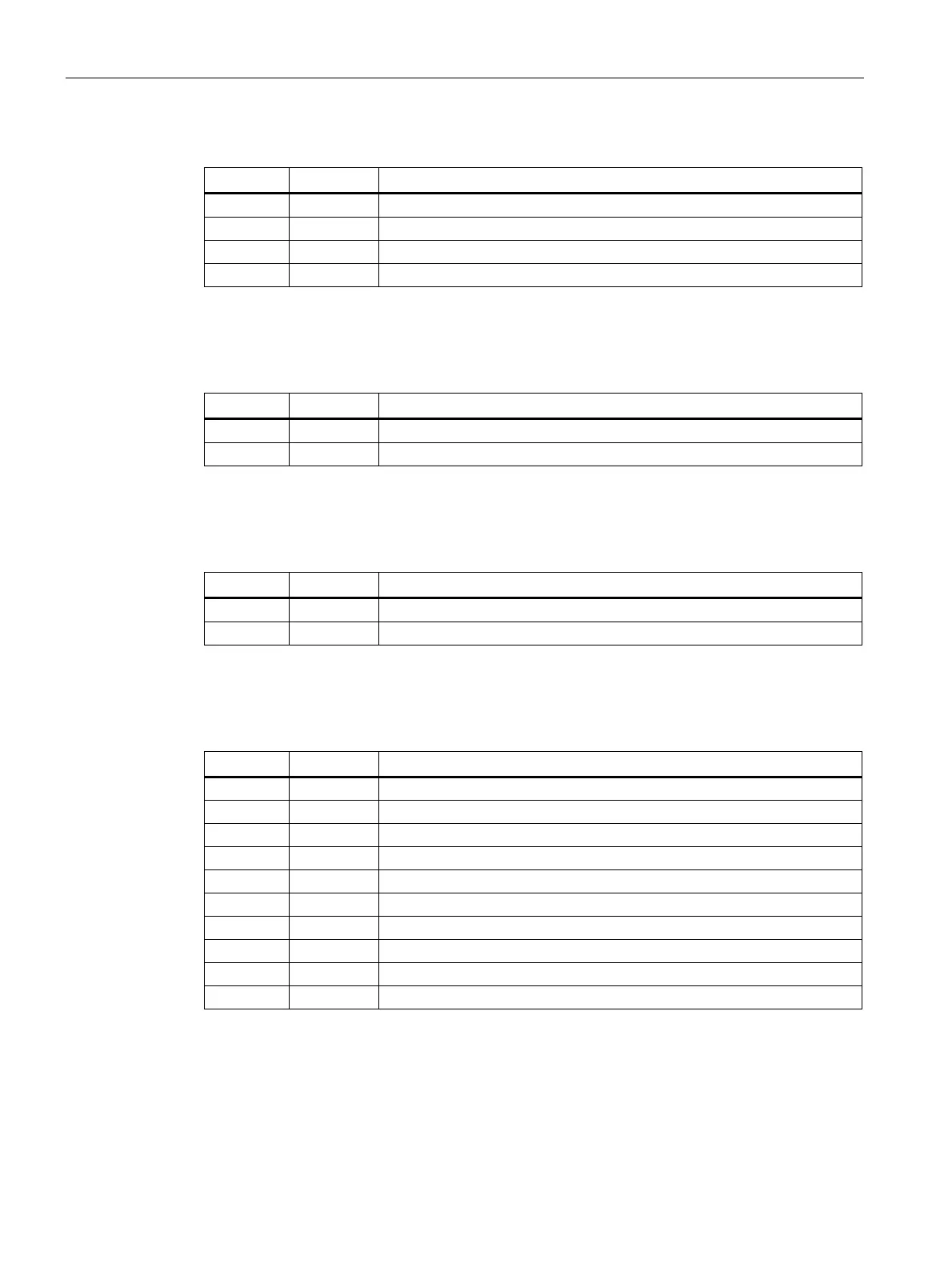
Table 8- 57 Format (107) "Switched-off I2t values"
Byte Bit Meaning
0 — Phase L1 (unsigned long)
4 — Phase L2 (unsigned long)
8 — Phase L3 (unsigned long)
12 — Phase N (unsigned long)
The table below shows the format (108) "Number of poles" that specifies the number of
protected poles for the main circuit.
Table 8- 58 Format (108) "Number of poles"
Byte Value Meaning
0 1 3-pole
0 2 4-pole (with N-conductor)
The table below shows the format (111) "Switch position DI" that also distinguishes the
switch position of the digital input module between Module 1 and 2.
Table 8- 59 Format (111) "Switch position DI"
Byte Value Meaning
0 1 Parameter set switching (Module #1)
0 2 6 x digital inputs (Module #2)
The table below shows the format (119) "Switch position DO" that specifies which output
block is selected with which delay.
Table 8- 60 Format (119) "Switch position DO"
Byte Value Meaning
0 0x01 Module #1 trip instantaneous
0 0x02 Module #1 trip delayed 200 ms
0 0x03 Module #1 trip delayed 500 ms
0 0x04 Module #1 trip delayed 1 s
0 0x05 Module #1 trip delayed 2 s
0 0x06 Module #2 alarm instantaneous
0 0x07 Module #2 alarm delayed 200 ms
0 0x08 Module #2 alarm delayed 500 ms
0 0x09 Module #2 alarm delayed 1 s
0 0x0A Module #2 alarm delayed 2 s
The table below shows the format (121) "Control DO outputs" for controlling the outputs of
the digital output modules with rotary coding switches.
 Loading...


