Product overview
2.3 Components
ET 200MP Distributed I/O System
18 System Manual, 01/2013, A5E03723484-01
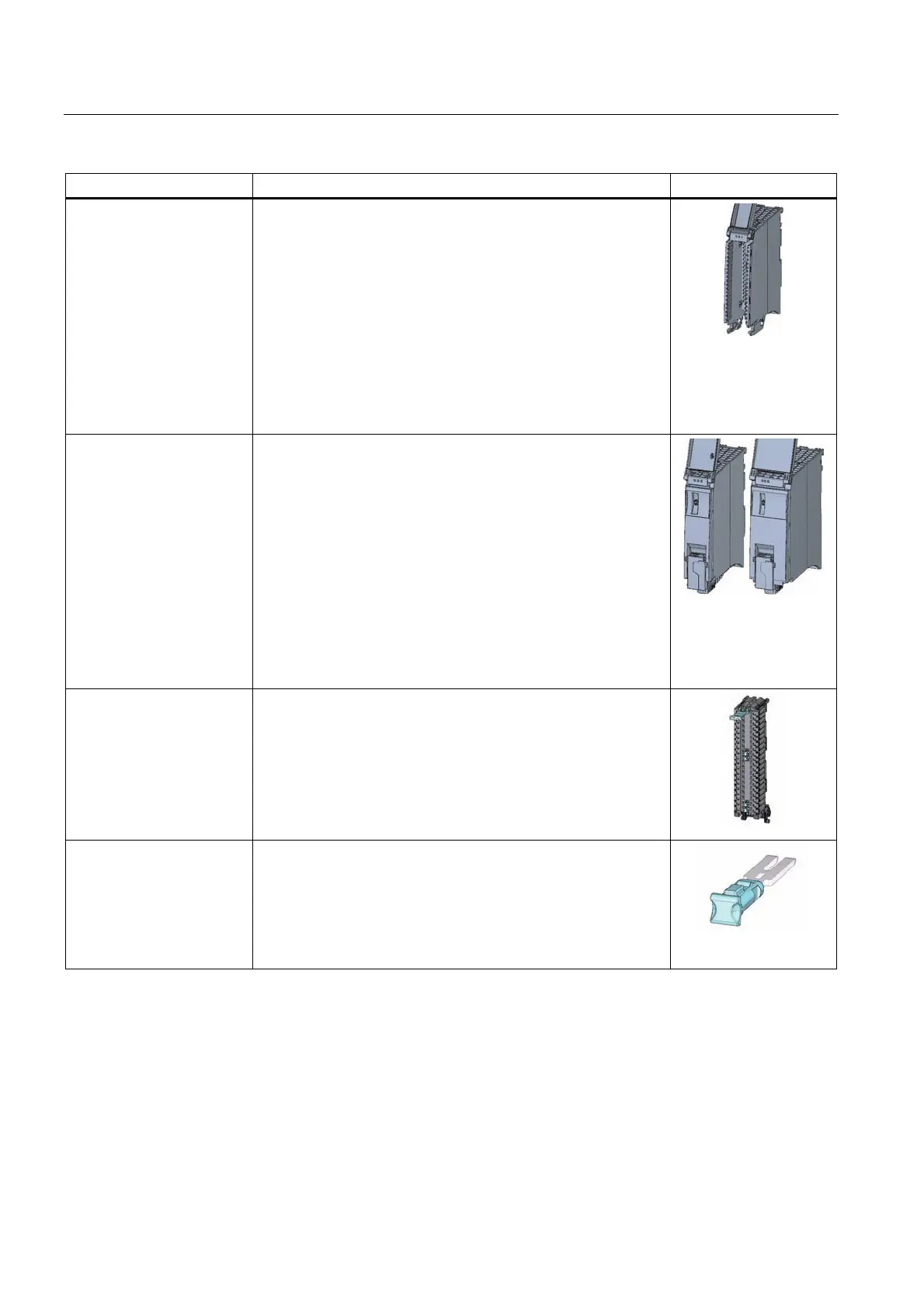
Components Function Diagram
I/O module The I/O modules form the interface between the controller and
the process. The controller detects the current process state via
the connected sensors and actuators, and triggers the
corresponding reactions. I/O modules are classified into the
following types of modules:
• Digital input (DI)
• Digital output (DQ)
• Analog input (AI)
• Analog output (AQ)
• Technology module (TM)
• Communication module (CM)
System power supply
module
The power supply module (PS) is required if the power supplied
by the interface module is insufficient.
As a component of the system power supply, the power supply
module increases the output at the backplane bus, and thus
allows the use of additional modules; it serves exclusively for the
power supply of the I/O modules and the interface module. Power
supply modules are available in three models:
• PS 25W 24V DC
• PS 60W 24/48/60V DC
• PS 60W 120/230V AC/DC
A power cable connector with coding element is included in the
scope of delivery of the power supply module, and may be
ordered as a spare part (Page 113).
Front connector The front connector serves for the wiring of the I/O modules.
The front connector for analog modules must be supplemented
with a shielding bracket, power supply element, and shielding
clamp. These components are included in the scope of delivery of
the analog module, and may be ordered as accessories
(Page 113).
Four potentia
l bridges and one cable tie are included in the scope
of delivery of the front connector.
Potential bridge for front
connector
With potential bridges, the provided supply voltage can be
bridged to the terminals on the opposite side (9 and 29, 10 and
30, 19 and 39, 20 and 40; only for digital modules with a
maximum rated voltage of 24 V DC). Voltage is present at these
terminals.
The potential bridges are included in the scope of delivery of the
front connector, and may be ordered as a spare part (Page 113).

 Loading...


