EasyManua.ls Logo

Siemens SIMATIC S7 - Input Wiring for Connecting Transducers to Channels 13 and

Siemens SIMATIC S7
336 pages
To Next Page IconTo Next Page
To Previous Page IconTo Previous Page
Loading...
Operation
IP244B
C79000–B8576–C865–01
3–20
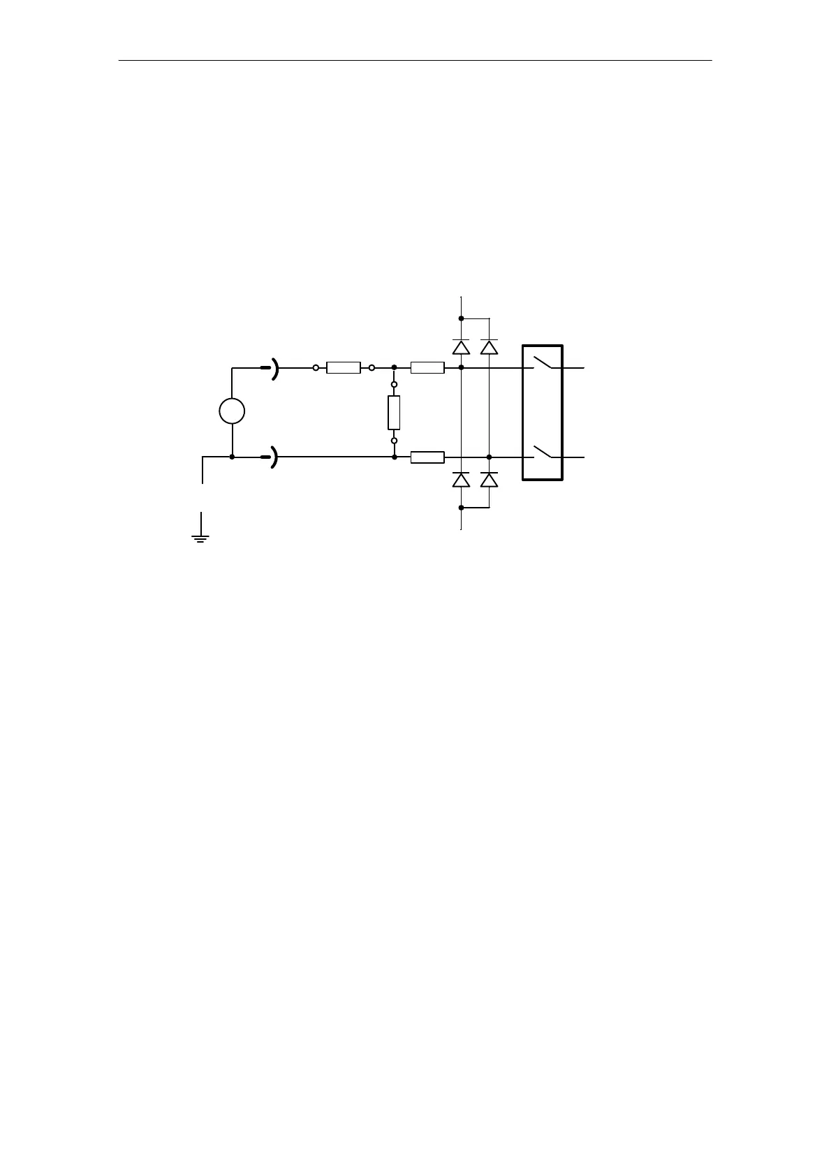
3.1.2 Input Wiring for Connecting Transducers to Channels 13 and 14
(0 ... 20.48 V = 2048 units resolution)
The resistors R
S
and R
P
are connected in series to the inputs, providing a voltage divider
(400:1). This yields a signal range of 0 ... 20.48 V.
  "!!&! "&! &$!%'$% $"   &" 
$!%'$
  
'&#($



!$"'! &$!%'$% )  '% % "! % & ( '  #"&!& $!

% !"& (

Table of Contents

Other manuals for Siemens SIMATIC S7

Related product manuals