Data Exchange with the Central Controller
4–25
IP244
C79000–B8576–C860–02
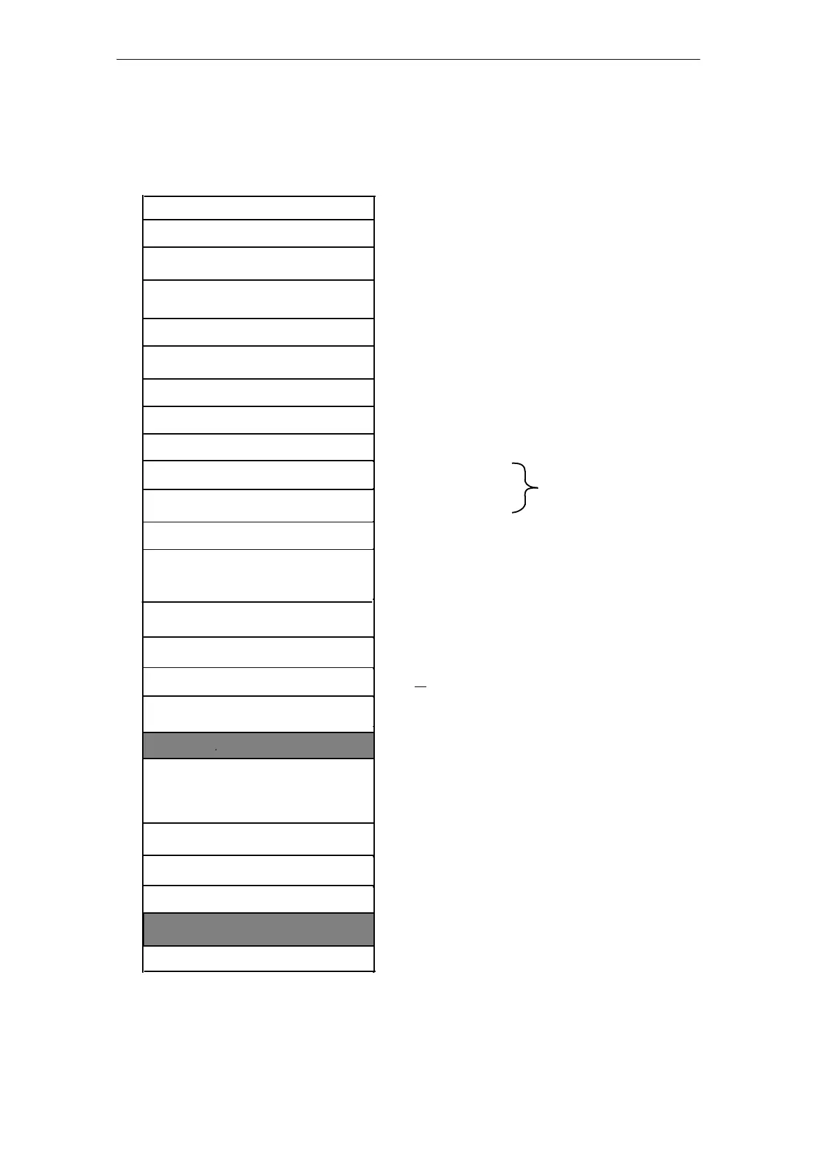
2.1 Messages 0 to 12 (Controller Parameters)
Each message contains the setpoints and the parameters for the individual controller. (The second
parameters sets are stored in messages 30 to 42.)
HeatingĆcooling parameters
Control byte 2
Manual manipulated variable
Limit value (C)
SelfĆtuning parameters
0 to 50 %, 1 unit = 1 %
0 to 255 %, 1 unit = 1 % only if main control byte 1,
bit 2=0, otherwise free
Temperature setpoint
1st positive tolerance
1st negative tolerance
Lower setpoint
2nd positive tolerance
2nd negative tolerance
Control byte 1
Gain K
R
(ST)
0 to 1600 °C in 1°CĆsteps
1 to 255 °Cin1°CĆsteps
0 to 1599 °C in 1°CĆsteps
1 to 255 °Cin1°CĆsteps
1 to 255 °Cin1°CĆsteps
0 to 100 % or 128 to 228 % for negative numbers, 1 unit = 1 %
1 to 25599,1unit = KR = 0.01
1 to 255 °Cin1°CĆsteps
Evaluation factor (C)
Free
Sampling time T
A
(ST)
0 to 255 ğ,
1 unit =1ğ
0 to 255 %, 1 unit = 1 %
350 to 65535 ms, 1 unit = 1ms
if main control byte 1, Bit 2=0 /or for cooling only
350 to 392700 ms, 1 unit = 10 ms
if main control byte 1, Bit 2=1 and no cooling controller is
selected
only for cascaded
control
Integral action time T
N
(ST)
Upper limit of control zone (ST)
or setpoint ramping
Lower limit of control zone (ST)
HeatingĆcooling ratio (ST)
Message number
0 or (T
A
T
N
512 T
A
), 1 unit = 4 s
0 or (T
A
T
D
512 T
A
), 1 unit = 1 s
2
0 to 12
Parameters marked with (ST) need not be specified for
controllers with selfĆtuning
Response value
1 unit = 10 ° C Checkback signal for selfĆtuning function
If temperature values
are specified in °F:
T [° F]=T [° C]·1.8+32
Parameters marked with (C) are only valid for
cascaded control
0
1
2
3
0 to 1600 °C/h, 0 to 3000 °C/h or 0 to 2047 °F/h
(= 1137 °C/h) (ramp slope)
With 3Ćstep controllers and main control byte 1,
bit 2 = 1 the upper limit of the control zone is relative
to 200° C (see pages 34 and 35)
0 to 1600° C
Minimum jump for 3Ćstep controllers
Checkback signal for selfĆtuning function
4
5
6
7
8
9
10
11
12
13
14
15
16
17
18
19
20
21
22
23
24
25
26
27
28
29
30
31
Derivative action time T
D
(ST)
Fig. 2.1/1 Structure of messages 0 to 12