Operation
2–27
IP244
C79000–B8576–C859–02
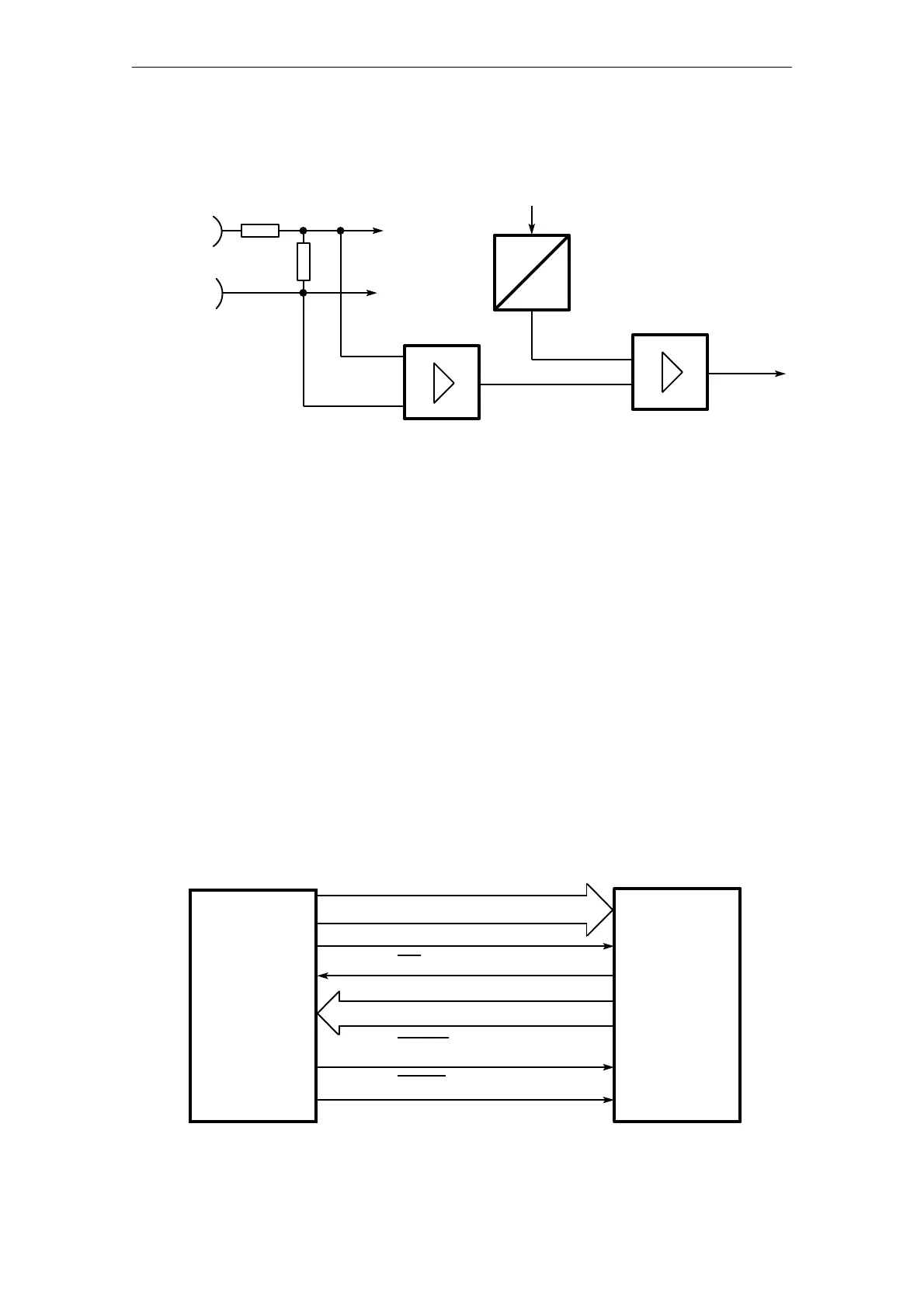
Fig. 3.2.2/1 Function diagram of the comparator channel
Output K
Limit value
Comparator
Actual value
P
2 1024 units = 10.24 V
= 0 to 25 mV
Channel 13
Differential
amplifier
Multiplexer
0 to 10.24 V
3.3 Interface to the CPU
Data is exchanged with the CPU according to the bus specifications for SIMATIC S5 systems.
The temperature controller module occupies 32 bytes in the address area of the CPU. By
writing a message number (0 to 63), 64 different data block messages each 31 bytes long can
be transferred from or to the CPU (see message structure). There are therefore 2048 bytes
available in the transfer RAM on the module for transferring parameters or measured values.
Function block FB 162 is available for assigning parameters and operating the module.
The address coding can be switched over from the S5 bus (PESP’ + 8 address lines) to PESP
+ 12 address lines (addressing jumper base A77). The data transfer with S5 can be in the form
of byte or word commands. There is no particular sequence necessary for the high and low
byte.
PESP'
ADB 0 to ADB 7 (ADB 11)
Fig. 3.3/1 Signal transfer
CPU Temperature
controller
244
RDY
DB 0 to DB 7
MEMWR
MEMRD