Data Exchange with the Central Controller
IP244
C79000–B8576–C860–02
4–38
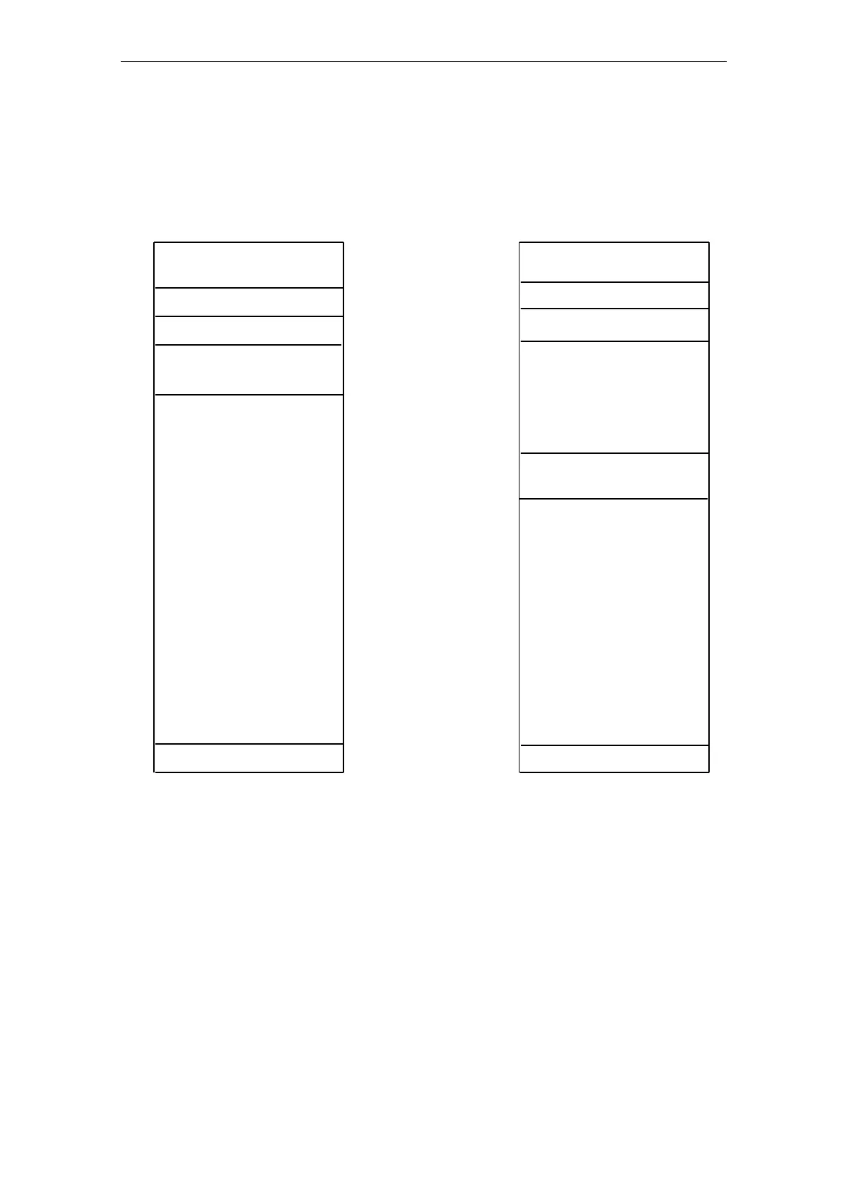
2.2 Messages 13 and 14
Messages 13 and 14 contain the setpoints and monitoring tolerances for the two voltage channels
13 and 14.
Negative tolerance
Positive tolerance
Setpoint
Negative tolerance
Reserved for heating current
acquisition
Positive tolerance
Fig. 2.2/1 Structure of message 13 and structure of message 14
Setpoint
Free
Message number (13)
0 to 2048, 1 unit = 10 mV
0 to 255, 1 unit = 10 mV
0 to 255, 1 unit = 10 mV
Reserved: must be 0
Message number (14)
Free
Free
0
1
2
3
4
5
6
7
8
9
10
11
12
13
14
15
16
17
18
19
20
21
22
23
24
25
26
27
28
29
30
31
0
1
2
3
4
5
6
7
8
9
10
11
12
13
14
15
16
17
18
19
20
21
22
23
24
25
26
27
28
29
30
31
Byte 0/1 Setpoint channels 13 and 14
The actual values read in via channels 13 and 14 are compared with the setpoint
and checked for tolerance violations.
Input: 0 to 1024 units = 10.24 V or 0 to 2048 units = 20.48 V.
Byte 2 Positive tolerance channels 13 and 14
If the actual value is higher than the setpoint plus the positive tolerance, an error
identifier is set (bit 0 in the corresponding error byte). By entering value 0, the
tolerance processing is disabled.
Byte 3 Negative tolerance channels 13 and 14
If the actual value is below the setpoint minus the negative tolerance, an error
identifier is set (bit 1 in the corresponding error byte). By entering value 0, the
tolerance processing is disabled.