Operation
3–25
IP244B
C79000–B8576–C865–01
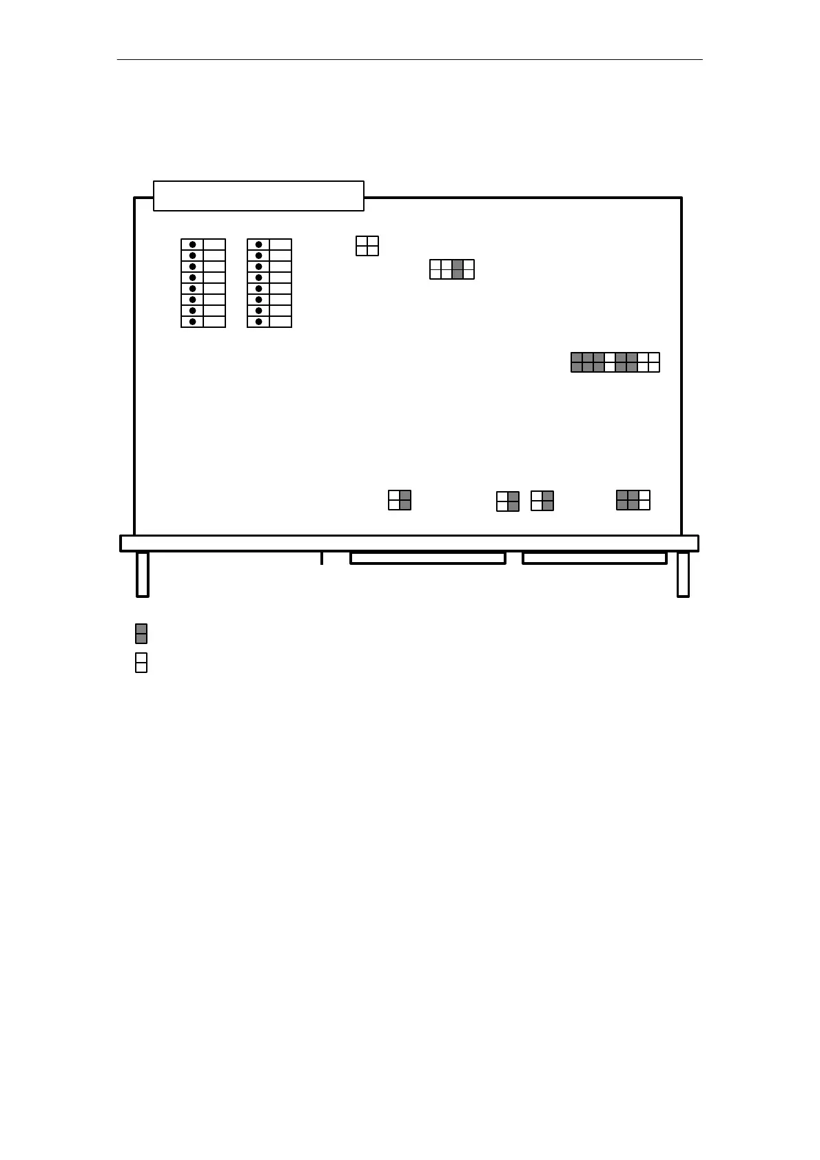
3.4 Switches and Jumpers
Fig. 3.4 Jumper settings upon delivery (thermal voltage measurement 51.2 mV)
A 76
1
2
3
4
5
6
7
8
A 77
X 4
DA
X 3
AE
X 5
L+
X1 bus connector
= Jumper inserted
= Jumper not inserted
offon offon
X12
2468
X6
3
4
1
2
X2
3
4
1
2
X9
3
4
1
2
X11X10
X8
31 5 7 9 111315
2 4 6 8 10121416
1357
3
4
1
2
5
6
3
4
1
2
X1 Backplane connector
X3 Front connector for analog inputs
X4 Front connector for digital outputs
X5 Connector for L+ load voltage
A76 Module address ADB 8-11 (DIL switch);
see Chapter 3.4.1
A77 Module address ADB 5-7 and PESP (DIL switch);
see Chapter 3.4.1
X6
X8 Jumpers; see next page
X12
X2 Thermocouple/ Pt 100 selection; see next page
X9 Mode channel 13
X10 Mode channel 14
X11 Mode channel 15