Operation
IP244
C79000–B8576–C859–02
2–24
3.1.4 Using the Module for Resistance-Type Sensors (Pt 100)
When using Pt 100s, the temperature controller module can only be operated with a maximum
of 8 channels. The sensors are supplied by the module via S+ and S–. A 4-wire connection is
required.
Mixed operation with thermocouples, or a combination of heating current measurement and the
special function is not possible.
To acquire values from resistance-type sensors, follow the procedure outlined below:
– switch over the input sensitivity to 512 mV/1024 mV (at X8 and X9)
– remove the voltage dividers for channels 13 and 14 and solder in jumpers for the series
resistor (R83 to R86, jumpers for R83 and R85)
– switch over channel 15 from the compensation mode to a normal input (at X8 and X9).
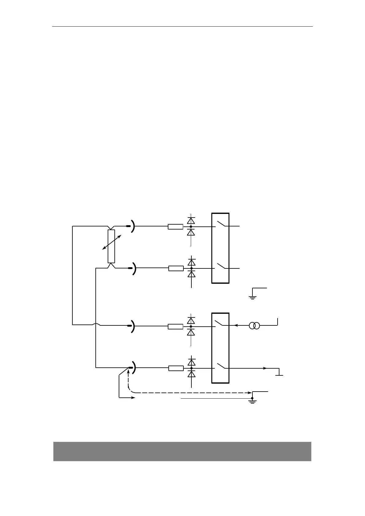
The necessary module configuration is described in Section 3.4. The wiring for a
resistance-type sensor can be seen in the following diagram.
&" +$
&
'&#*$
"!%&
+$
! !&
$$! #"&!&
Fig. 3.1.4/1 Wiring for resistance-type sensors
The connection from S– to the M-bar is necessary to remain below the maximum potential
difference U
CM
of 1 V
PP
.
! "#$&! )& & % & " #$&"$ %% % !! % "!($& &"
'$$!& "'&#'&