EasyManuals Logo

Siemens SIMATIC S7 User Manual

Siemens SIMATIC S7
336 pages
To Next Page IconTo Next Page
To Previous Page IconTo Previous Page
Page #23 background imageLoading...
Page #23 background image
Operation
2–21
IP244
C79000–B8576–C859–02
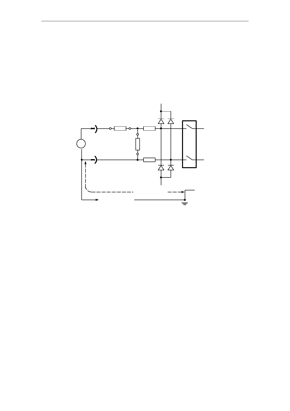
3.1.2 Wiring the Inputs for Channels 13 and 14 to Connect Transducers
(0 to 20.48 V = 2048 Units Resolution)
The inputs have resistors R
S
and R
P
connected as voltage dividers (400:1). This allows a signal
range of 0 to 20.48 V. Other voltage ranges require other voltage dividers.
Fig. 3.1.2/1 Connecting floating transmitters from 0 to 20.48 V
R
S
Transmitter
0 to 20.48 V
R
P
-
+
-
+
Multiplexer
-
+
M-
M+
to MĆbar
0 V, MĆbar
in cabinet
(reference potential)
=
Channel 13:
R
S
= R83
R
P
= R84
Channel 14:
R
S
= R85
R
P
= R86
U
CM
1 V
PP

Table of Contents

Other manuals for Siemens SIMATIC S7

Questions and Answers:

Question and Answer IconNeed help?

Do you have a question about the Siemens SIMATIC S7 and is the answer not in the manual?

Siemens SIMATIC S7 Specifications

General IconGeneral
BrandSiemens
ModelSIMATIC S7
CategoryController
LanguageEnglish

Related product manuals