Notes on Controller Settings
4–139
IP244
C79000–B8576–C860–02
4.7 Determining the System Parameters for Purely Cooling
Controllers (when Control Byte 1, Bit 0 = 0 and Bit 2 = 1)
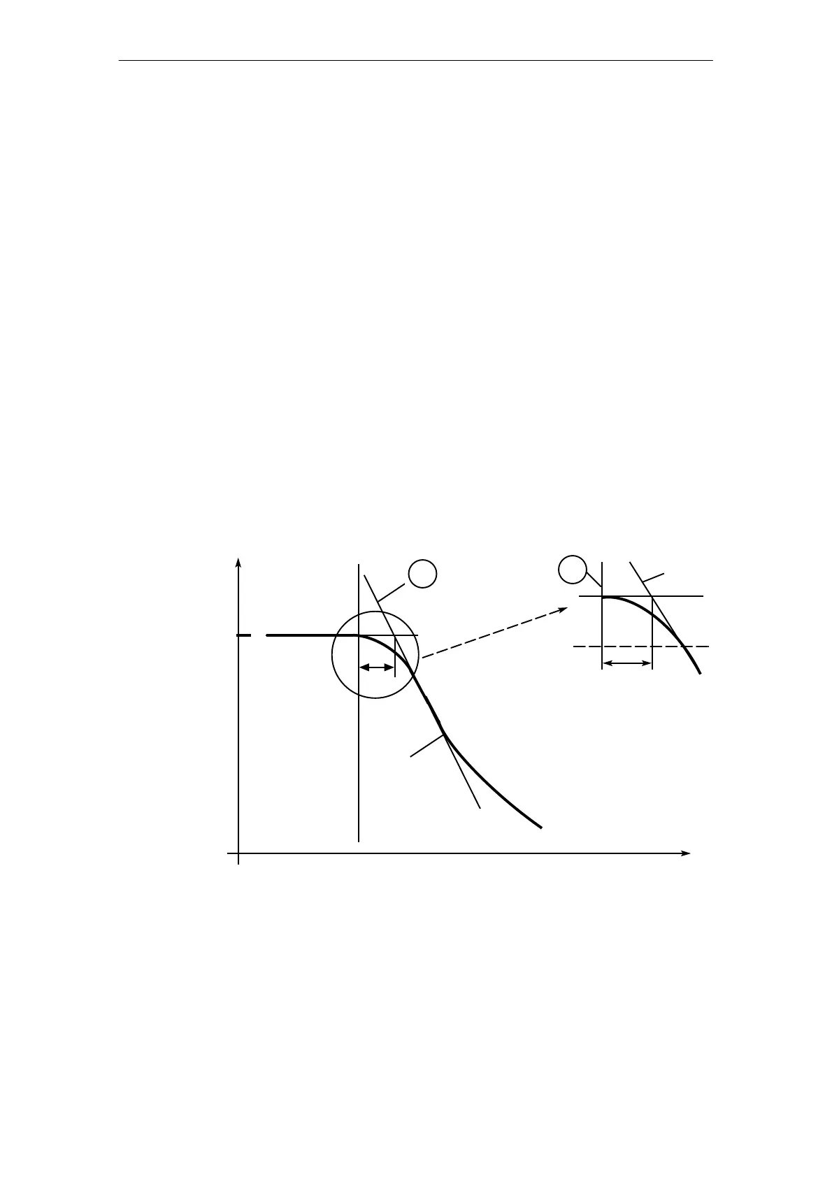
The cooling response of the temperature-controlled system is plotted with a recorder (see also
Fig. 4.8/1).
The procedure is as follows:
enter non-critical control parameters:
T
A
= 0.8 s (numerical value 800)
K
R
= 1 (numerical value 100)
T
N
, T
D
= 0
Upper limit of the control zone = 30 C
Lower limit of the control zone = 30 C
– Enter setpoint temperature = 0 C
– Allow the temperature to settle to the operating temperature, dependent on external heating
energy supply (e.g. by neighboring heating zones).
– Enter setpoint temperature = 1 C
➀.
– The module switches the cooling on.
Caution: during the cooling process the external supply of heating energy must remain
constant (i.e. neighboring heating zones must heat with a constant manipulated
variable).
Temperature
Time
Fig. 4.8/1 Recorded cooling curve
The parameters can then be determined from the curve:
T
U
= delay time (in s)
S
K
= maximum slope of the cooling curve (in C/s)
T
sta
= start temperature (in C).
– The temperature T
COOL
(in C) of the cooling medium must also be determined.