Operation
IP244
C79000–B8576–C859–02
2–32
3.4.1 Setting the Module Address
Each IP 244 temperature controller module requires 32 addresses for transferring the required
parameters. You only need to set the start address of the module. The following 31 addresses
are then automatically occupied and no longer available for other modules. The addresses can
be set in steps of 32.
P
E
S
P
2
8
2
9
2
10
2
11
256
Gap
2
8
to
2
11
2
5
2
6
2
7
32 64 128
87654321
Gap
PESP
87654321
DIL switch A 76 DIL switch A 77
for ADB 8 to 11 for ADB 5 to 7
Process area
Q area
S5Ć135 U
S5Ć155 U
S5Ć115U
(CPU 945)
only in EU
P area
all PLCs
ABS area
S5Ć115 U
Switch A 77
No. EU CC
5 off on
7onon
8onon
5 off on
7onon
8onon
5onon
7onon
8 off off
Baugruppenadresse
Einstellen Bereich
über 0..224
A 77
über 128..224
A 77
über 0..224
A 77
Switch A 76
EU CC
2
8
to 2
11
2
8
=on
= off 2
9
to 2
11
= off
2
8.
to 2
11
2
8
to 2
11
= off = off
2
8
to 2
11
2
8
to 2
11
= off = off
Module address
Set Range
at 0 to 224
A 77
at 128 to 224
A 77
at 0 to 224
A 77
Address parameter
for FB 162
0
1
2
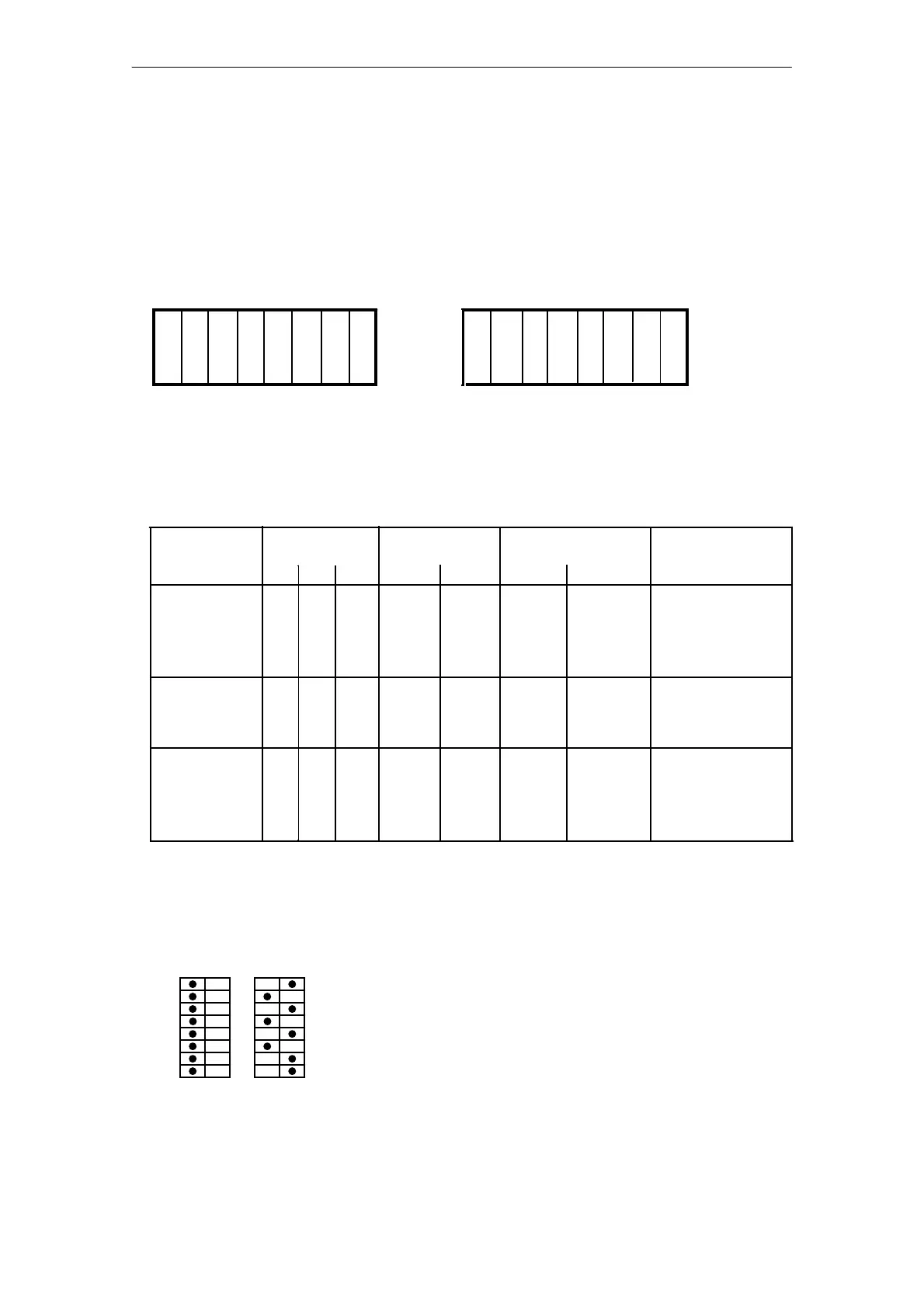
Example:
you wish to assign the start address n = 160 in the normal I/O area P of the central controller.
The switches must then be set as shown below:
A 77A 76
The next module can then be assigned the start
address 192 (160 + 32).
1
2
3
4
5
6
7
8
offonoffon