Installing and connecting the device
3.3 Mounting the PRO device
IFP V2, IFP V2 PRO, IFP V2 ETH
Operating Instructions, 03/2023, A5E46641410-AE
49
• One of the following support arm or pedestal systems:
– Support arm or pedestal with mechanical VESA interface and the corresponding
Siemens adapter set
– Support arm or pedestal with mechanical interface for the Siemens base adapter
The type of mechanical interface differs depending on the type of support arm or
pedestal.
See also section "System components for PRO devices (Page 20)".
• Torque screwdriver with T20 insert
• The following cables are fed through the pedestal or the support arm to which the device
is mounted:
– Equipotential bonding cable
– Power supply cables
– Data cables, e.g. USB, DisplayPort or Ethernet cable
Procedure
This section describes the mounting of the device to a support arm system using example
figures. Installation on a pedestal is carried out in the same way. With PRO devices for support
arm (not extendable, flange top), the base adapter is screwed to the device from the top.
With PRO devices for pedestal (extendable, flange bottom), the base adapter is screwed to
the device from the bottom. A device for a support arm system cannot be used on a pedestal,
and vice versa.
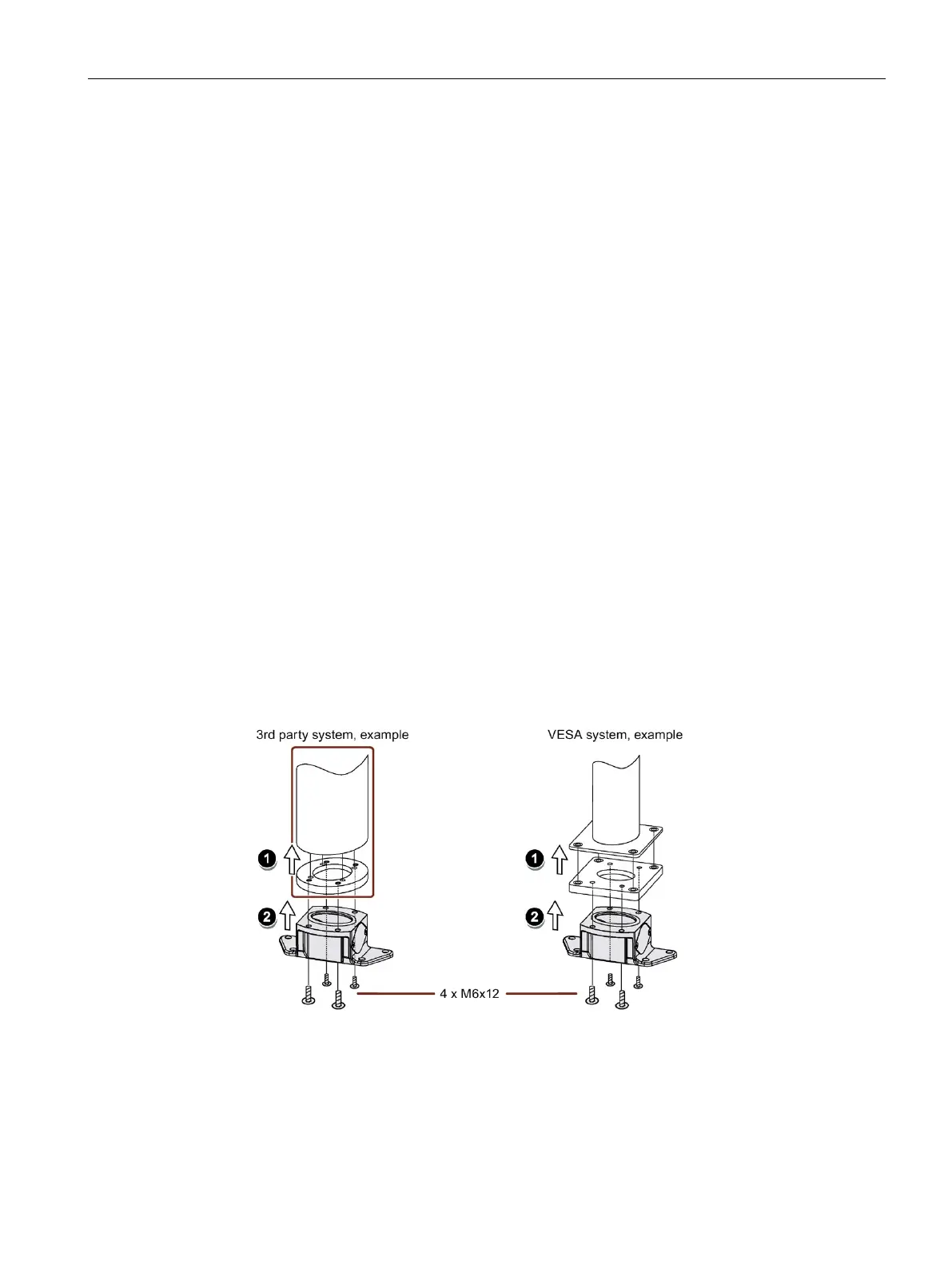
1. If an adapter plate for the Siemens base adapter is included in your support arm system,
attach the adapter plate to the support arm with 4 M6x12 screws. Observe the torque that is
specified for the support arm.
2. Attach the base adapter with 4 M6x12 screws to the mechanical interface of the support
arm from below. Observe the torque that is specified for the support arm.