Installing and connecting the device
3.5 Connecting the device
IFP V2, IFP V2 PRO, IFP V2 ETH
66 Operating Instructions, 03/2023, A5E46641410-AE
Mount the ferrites as close as possible to the connectors and in a position that allows the
Cat. 6A Ethernet cable to be secured at the strain relief plate, see section "Securing cables at
the IFP (Page 70)".
Observe the following in extended mode:
• The cable shield of the Cat. 6A Ethernet cable must be connected to the equipotential
bonding rail, see section "Equipotential bonding (Page 58)".
• A ferrite is also required for the power supply lines, see section "Connecting the power
supply (Page 61)".
• If the Transceiver Unit is mounted on a standard mounting rail, then hold the
Transceiver Unit firmly at the top while connecting the plugs.
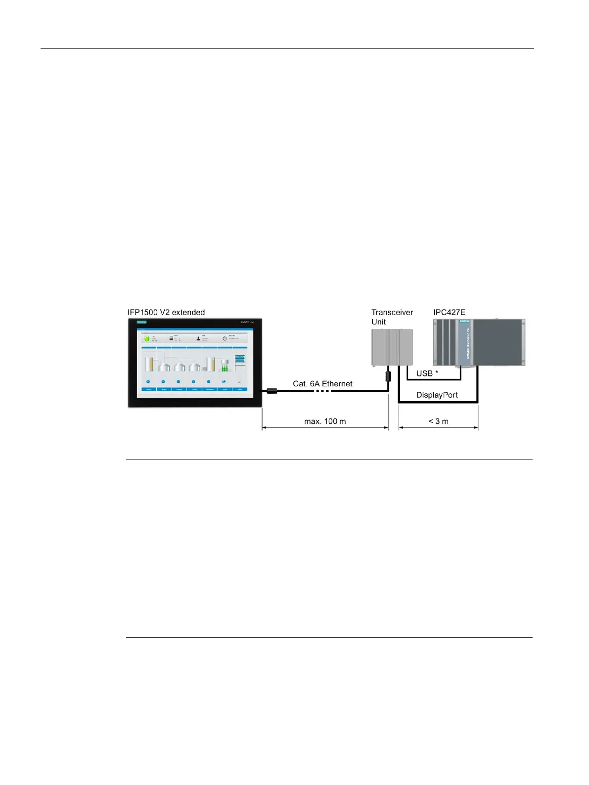
Wiring diagram
The following figure shows an example of the connection of an IFP1500 V2 extended via the
Transceiver Unit to an IPC427E and is generally valid for all extended versions and PRO
devices in connection with a corresponding PC.
USB cable Type B connector - Type A connector
Possible number of extended versions or PRO devices on a PC
A free USB interface and a free DisplayPort interface of the PC are required for each
connection of an extended version or a PRO device to a PC via the Transceiver
Unit. This
means that the possible number of IFPs on a PC is defined by the number of availa
ble USB
and DisplayPort interfaces of the PC. A Transceiver
Unit is required for each extended version
Possible number of PCs on an extended version or a PRO device
-Link interface of an extended version or a PRO device is connected to a PC
Unit, no video signals can be transmitted via the DisplayPort interface of
the IFP. This means that exactly one PC can be connected to one extended version or one PRO
device.