Thread depth and screw-in depths in the primary section
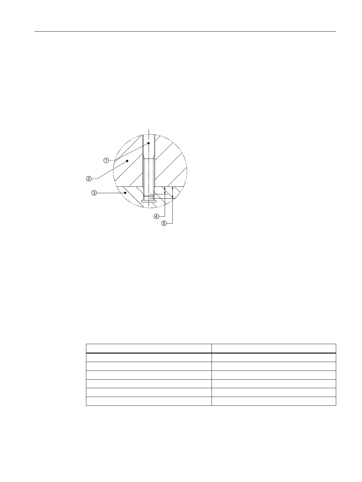
The following drawing schematically illustrates the minimum permissible and maximum screw-
in depth of the xing screws in the screwed-in state. For selecting the screw length, a good
range is thus made available to the machine manufacturer.
The selection of the length of the mounting screws while taking all of the design tolerances
into consideration is the responsibility of the machine manufacturer.
The machine manufacturer must ensure that the minimum screw-in depth is reached and the
maximum screw-in depth is not exceeded.
① Mounting screw ④ Minimum screw-in depth: 8
-2.0
mm
② Slide ⑤ Maximum screw-in depth: 8
+0.0
mm
③ Primary section
Figure5-1 Schematic diagram for the screw-in depths in the primary section
Screw-in depthsfor the secondary section installation
Minimum permissible screw-in depth
The minimum permissible screw-in depths for the most commonly used materials for a
machine bed are listed below. For dierent materials, you must determine the screw-in depth
according to VDI Directive 2230.
Table 5-2 Minimum permissible screw-in depths
Material Screw-in depth
ENGJL‑250 1.4•d
ENGJL‑300 1.3•d
ENGJS‑600‑3 0.7•d
G‑ALZN10Si8Mg 2.8•d
St37 1.8•d
St50 1.3•d
Maximum screw-in depth
The maximum screw-in depth is at the discretion of the machine manufacturer.
Installation
5.2Specications for mounting linear motors
Naturally-Cooled 1FN3 Linear Motors
Operating Instructions, 06/2023, A5E52220465B AB 61