6.4 Power connection
Table 6-2 Power connection - single cores
Color/identication Connection
green/yellow PE
black U
blue V
red W
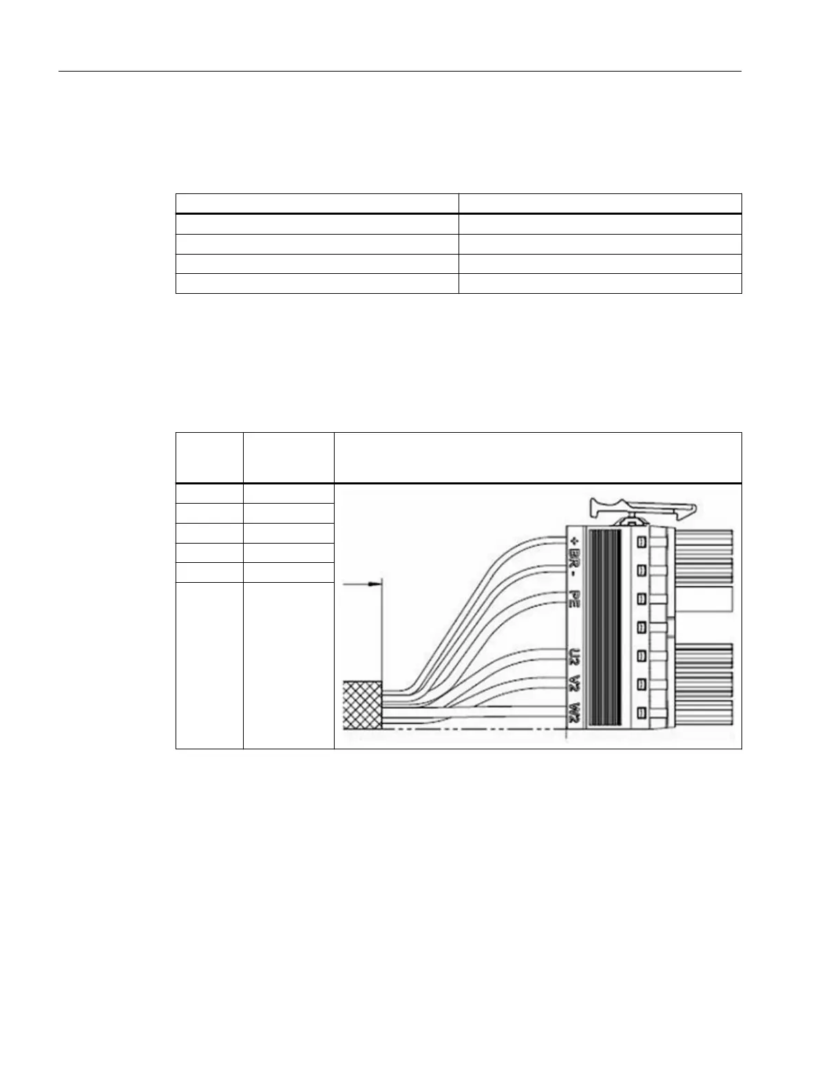
The terminal assignment from the following table is applicable for subsequently mounted
connectors:
• Connector 6SL3162-2MA00-0AC0 with screw terminals
• Connector 6SL3162-2MB00-0AC0 with spring-loaded terminals
Table 6-3 Terminal assignment power connectors for motor modules, types C and D
Connec‐
tion
Screw/
spring-loa‐
ded terminal
Terminal assignment power connector
U U2
V V2
W W2
PE PE
- BR-
- BR+
Cable protection when primary sections are connected in parallel
For the following congurations, you require a circuit breaker for each primary section:
• Several primary sections are connected in parallel to one Motor Module.
• The current-carrying capacity of the feeder cable cross-section is less than the rated current
of the Motor Module.
Electrical connection
6.4Power connection
Naturally-Cooled 1FN3 Linear Motors
92 Operating Instructions, 06/2023, A5E52220465B AB