Operation (hardware)
2.2 Operator controls
SIMOTION D4x5-2
Manual, 11/2010
33
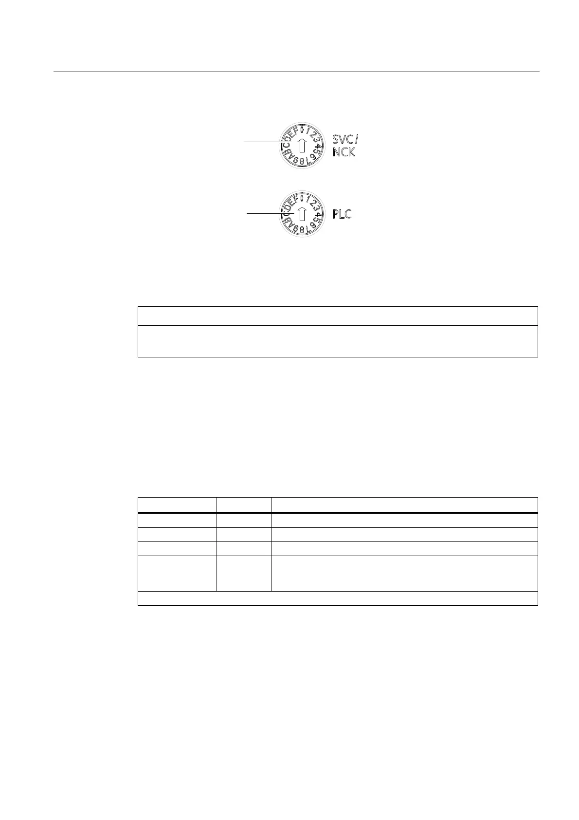
0RGHVHOHFWRU
6HUYLFHVHOHFWRU
VZLWFK
Figure 2-3 Selector switches for service and operating modes of the SIMOTION D4x5-2
CAUTION
Always use an insulated screwdriver to turn the rotary switch. Otherwise, static electricity
can destroy the switch.
Mode selector
The following table contains the possible mode selector positions and the associated LED
displays. The mode selector positions are explained in the order in which they are arranged
on the SIMOTION D4x5-2.
Table 2- 1 Mode selector position
Selector position Meaning LED
0 RUN RUN
1 STOPU SU/PF
2 STOP STOP
3 MRES The MRES operating modes are indicated via the STOP LED.
(ON/OFF/flashing, see
SIMOTION D4x5-2
Commissioning and
Hardware Installation Manual)
Other selector positions are not assigned