Supplementary system components
6.3 TB30 terminal board
SIMOTION D4x5-2
Manual, 11/2010
87
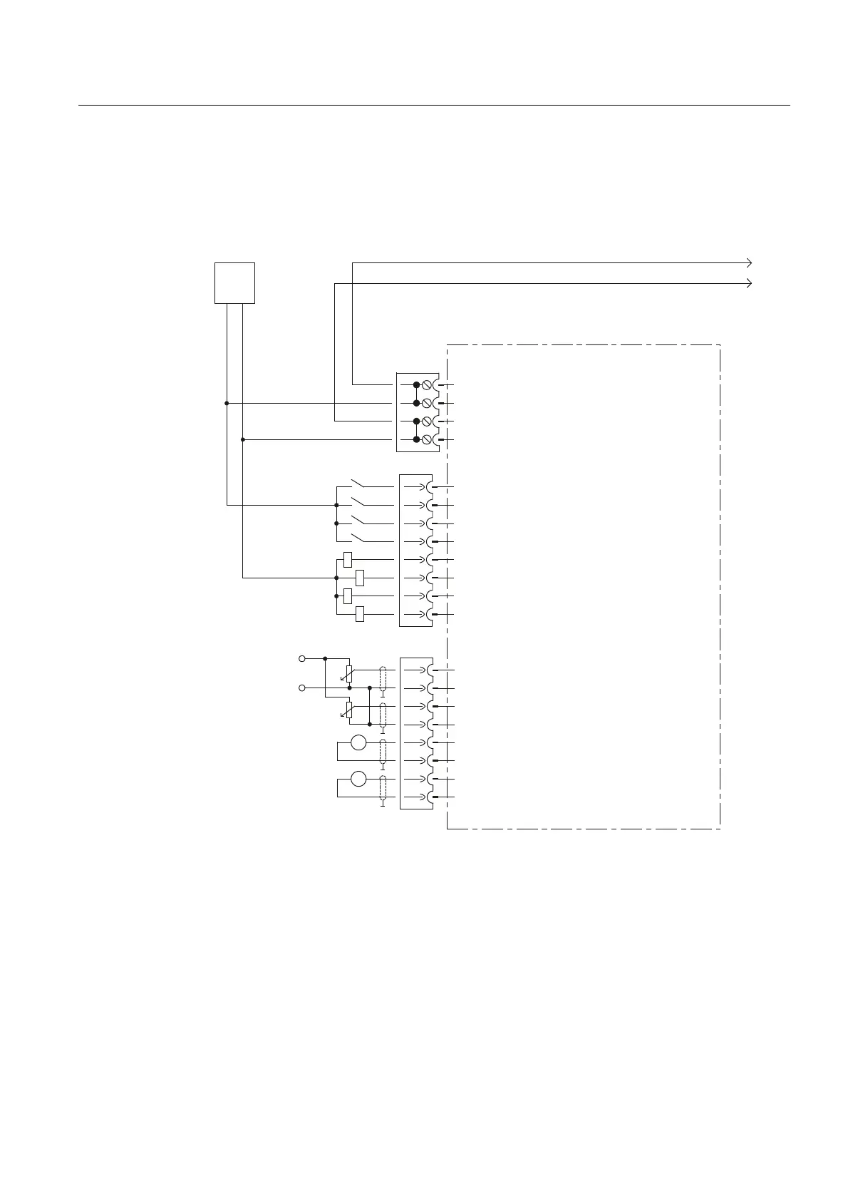
6.3.3.2 Connection diagram
The following figure shows the schematic diagram of the TB30 as well as its connections for
inputs (DI, AI), outputs (DO, AO) and power supply.
'2
'2
'2
'2
',
',
',
',
s9
$2
$2
$2
$2
$,
$,
$,
$,
9
9
0
0
0
0
9
0
0
([W
9
7%WHUPLQDOERDUG
;
;
;
Figure 6-6 TB30 connection diagram