Interfaces
3.5 Digital inputs/outputs
SIMOTION D4x5-2
50 Manual, 11/2010
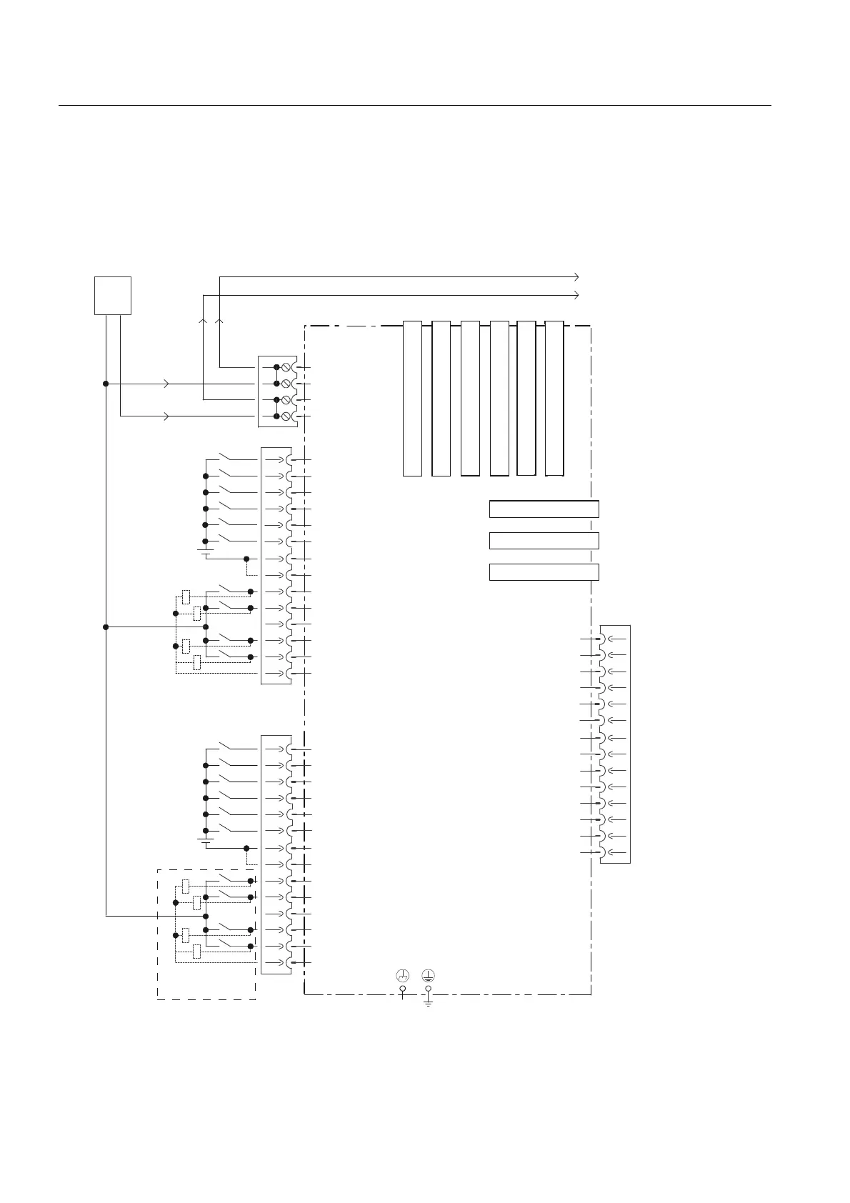
Connection and circuit diagram for SIMOTION D4x5-2
The following figure shows the connection and circuit diagram of the digital inputs and
outputs on the D4x5-2.
352),%86'3
'5,9(&/L4VRFNHW
'5,9(&/L4VRFNHW
'5,9(&/L4VRFNHW
'5,9(&/L4VRFNHW
'5,9(&/L4VRFNHW
'5,9(&/L4VRFNHW
6,027,21'[
352),%86'3
-XPSHURSHQPHDQVHOHFWULFDO
LVRODWLRQIRUGLJLWDOLQSXWV',
&DQEHSDUDPHWHUL]HGDV
LQSXWRXWSXWIRUHDFKFKDQQHO
([W
9
352),1(7,2
'HWDLO$
3LQZLULQJDV','2VHH'HWDLO$
5HVHUYHG
5HVHUYHG
0
0
9
0
0
','2
','2
','2
','2
0
0
',
',
',
',
0
0
','2
','2
','2
0
0
',
',
',
',
','2
;;; ; ; ;
0
;
0
;
;
0
0
;
;
;
333
',
',
',
',
0
0
0
,1287
,1287
0
,1287
,1287
,1287
,1287
,1287
,1287
;
Figure 3-5 Connection and circuit diagram of the digital inputs/outputs

 Loading...


