Interfaces
3.7 PROFIBUS DP interfaces
SIMOTION D4x5-2
Manual, 11/2010
57
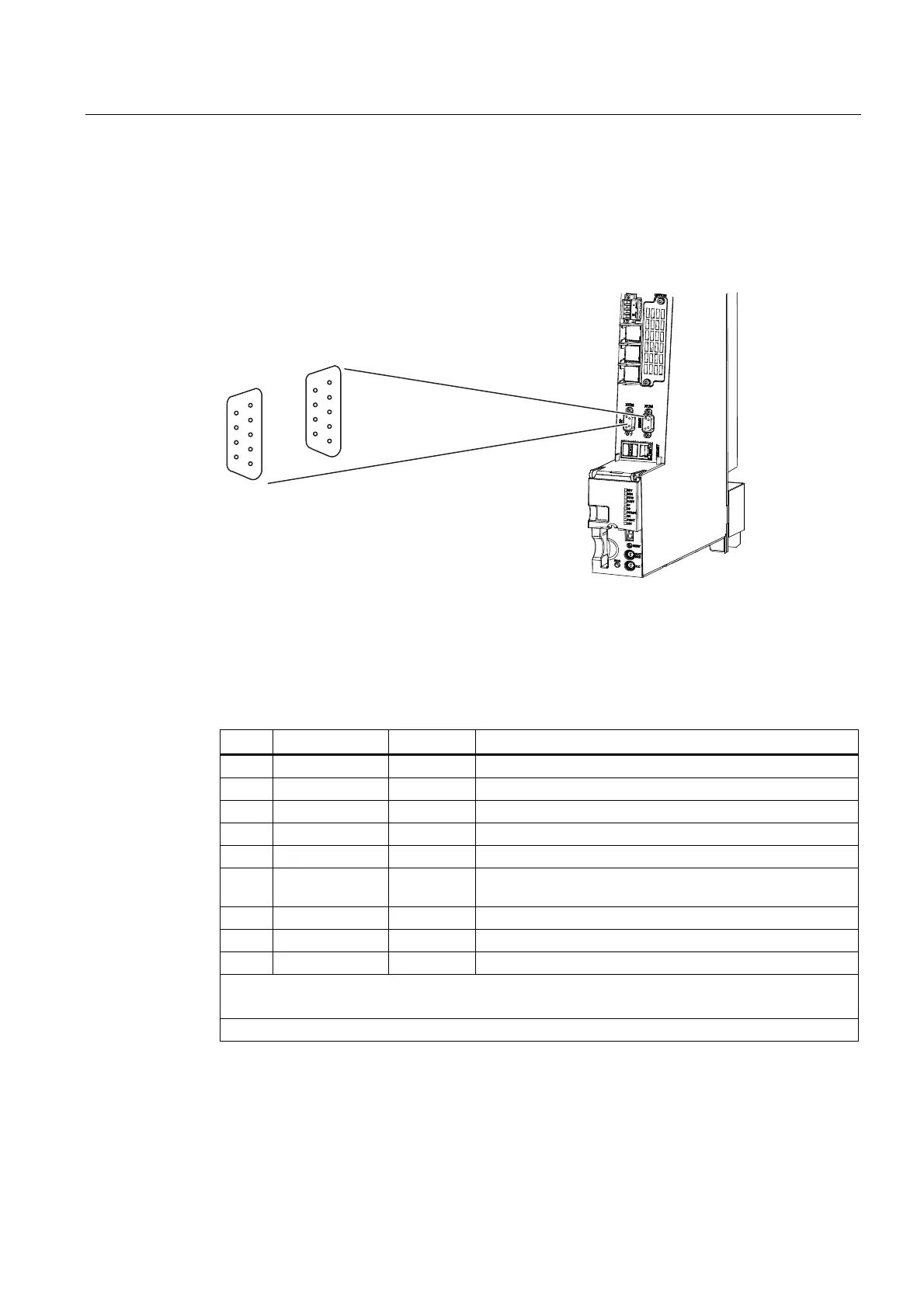
Position of connectors
The following figure shows the mounting position and designation of the connectors on the
control unit.
'303,
;;
'3
Figure 3-7 Position of the PROFIBUS interfaces X126, X136
Interface assignment for X126
Table 3- 17 PROFIBUS DP interface X126
Pin Signal name Signal type Meaning
1 -- -- Reserved, do not use
2 M VO Ground to P24_SERV
3 1RS_DP B RS-485 differential signal
4 1RTS_DP O Request to send
5 1M VO Ground to 1P5
6 1P5 VO 5 V power supply for bus terminal, external, short-circuit
proof
7 P24_SERV VO 24 V for teleservice, short-circuit proof, 150 mA maximum
8 1XRS_DP B RS-485 differential signal
9 -- -- Reserved, do not use
The 1P5 voltage is provided exclusively for the bus terminal.
No OLPs are permitted.
Signal type: VO = Voltage output (power supply) O = Output B = Bidirectional

 Loading...


