EasyManua.ls Logo

Siemens SIMOTION D410-2 DP User Manual

Siemens SIMOTION D410-2 DP
336 pages
To Next Page IconTo Next Page
To Previous Page IconTo Previous Page
Page #100 background imageLoading...
Page #100 background image
The states that can occur during operation are described in the following.
Table 5-8
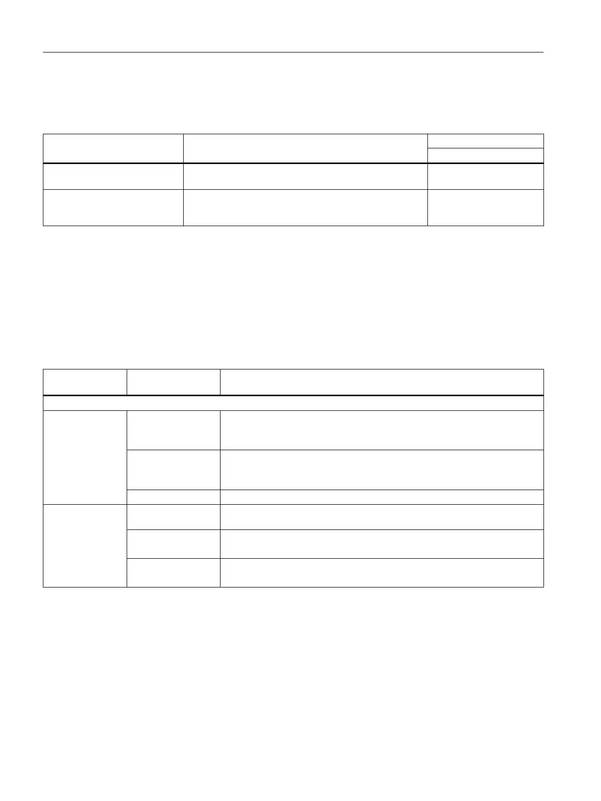
Overview of fan states
State PeripheralFaultTask System variable
1)
_cpuDataRW.fanWarning
The fan fails in the STOP operat‐
ing state, then RUN
PeripheralFaultTask:
Is not called
=YES
The fan fails in the RUN operat‐
ing state
PeripheralFaultTask:
TSI#InterruptId = _SC_PC_INTERNAL_FAILURE (= 205)
TSI#details = 16#00000080
=YES
1)
The "YES" value must be reset to "NO" by the application.
Requirement for/presence of a fan
System variables can be used to evaluate:
Whether a fan is required for the operation of the device (or not)
Whether a fan is installed (or not)
Table 5-9 System variable fannecessary/fanexisting
System variable
on the device
States Description
fanbattery of data type StructDeviceFanBattery (the system variables are of the data type EnumFanBattery)
.fannecessary
1)
MANDATORY Fan is required for operation of the device. .fanexisting can be used to query
whether a fan is installed.
Examples: D410-2, D445-2, D455‑2
OPTIONAL Fan can be used optionally. .fanexisting can be used to query whether a fan is
installed.
Examples: D425, D435
NOT_MANDATORY Fan is not required for operation of the device.
.fanexisting
1)
SINGLE A single fan is installed
Examples: D410-2
REDUNDANT Double fan is installed.
Examples: D445‑2, D455‑2
NOT_EXISTING No fan is installed.
Example: D425 and D435 without optional fan.
1) Value is statically set to MANDATORY/SINGLE in the SIMOTION D410-2.
SIMOTION D410-2 only detects an unplugged fan indirectly.
The system variable fanexisting has statically the state SINGLE for the SIMOTION D410-2 .
If the module temperature increases to impermissible values due to a fan having been
unplugged, the module signals overtemperature.
The fan speed is available in system variable _cpuData.fanRpm as of V4.4.
Commissioning (hardware)
5.7 Fan
SIMOTION D410-2
100 Commissioning and Hardware Installation Manual, 01/2015

Table of Contents

Question and Answer IconNeed help?

Do you have a question about the Siemens SIMOTION D410-2 DP and is the answer not in the manual?

Siemens SIMOTION D410-2 DP Specifications

General IconGeneral
Product type designationSIMOTION D410-2 DP
TypeController
Supply voltage24 V DC
Input Voltage24 V DC
Protection ClassIP20
Power Supply24 V DC
Communication InterfacesPROFINET, PROFIBUS
Operating Temperature0 to 55 °C
ProgrammingSCOUT

Summary

Safety instructions

Fundamental safety instructions

Details general safety instructions and warnings related to electrical devices and hazards.

Specific safety information for SIMOTION D410-2

Provides specific safety information relevant to the SIMOTION D410-2 device.

Installing

General requirements

Covers general requirements for installation, including mounting options and open components.

Mounting the SIMOTION D410-2 on the power module

Provides instructions for mounting the SIMOTION D410-2 onto the SINAMICS S120 Power Module.

Mounting the SIMOTION D410-2 on the mounting plate

Describes how to mount the SIMOTION D410-2 separately using a mounting plate.

Connecting

Protective conductor connection and potential equalization

Details requirements and procedures for protective conductor connection and equipotential bonding.

Connecting the power supply

Covers safety rules and wiring procedures for connecting the power supply.

Connecting DRIVE-CLiQ components

Explains how to connect DRIVE-CLiQ components and lists wiring rules.

Connecting I/Os

Describes how to connect I/Os, required tools, and switching analog input settings.

Connecting PROFIBUS/MPI

Covers PROFIBUS connection components, cables, connectors, and length rules.

Connecting PROFINET IO components (D410-2 DP/PN only)

Details wiring, mixed operation of IRT/RT, and PROFINET cables and connectors.

Commissioning (hardware)

Inserting the CompactFlash card

Explains the characteristics and procedure for inserting the CompactFlash card.

Switching on the power supply

Details the procedure for powering up the control unit and its behavior.

Parameter assignment / addressing

Creating a project and configuring the communication

Guides through creating a project and configuring communication interfaces like PROFIBUS, PROFINET, Ethernet.

Configuring PROFIBUS DP

Provides general information, master-slave configurations, address assignment, and cycle clocks for PROFIBUS DP.

Configuring PROFINET IO

Explains communication cycles, sync domains, signal propagation delays, and addressing for PROFINET IO.

Commissioning (software)

Overview of commissioning

Lists requirements and steps for software commissioning, including symbolic assignment.

Performing an offline configuration

Details the process of creating a project and configuring components offline.

Performing an online configuration

Guides through establishing online connections and automatic configuration.

Optimizing the drive and controller

Explains automatic and manual methods for optimizing drive and controller parameters.

Configuring Safety Integrated functions

Details integrated safety functions, including basic and extended functions, and PROFIsafe.

Service and maintenance

Replacing modules

Provides procedures for removing, replacing, and installing modules, including spare parts.

Performing a firmware and project update

Covers various options for updating firmware and projects, including preparatory measures.

Diagnostics

ESD guidelines

Related product manuals