● Used
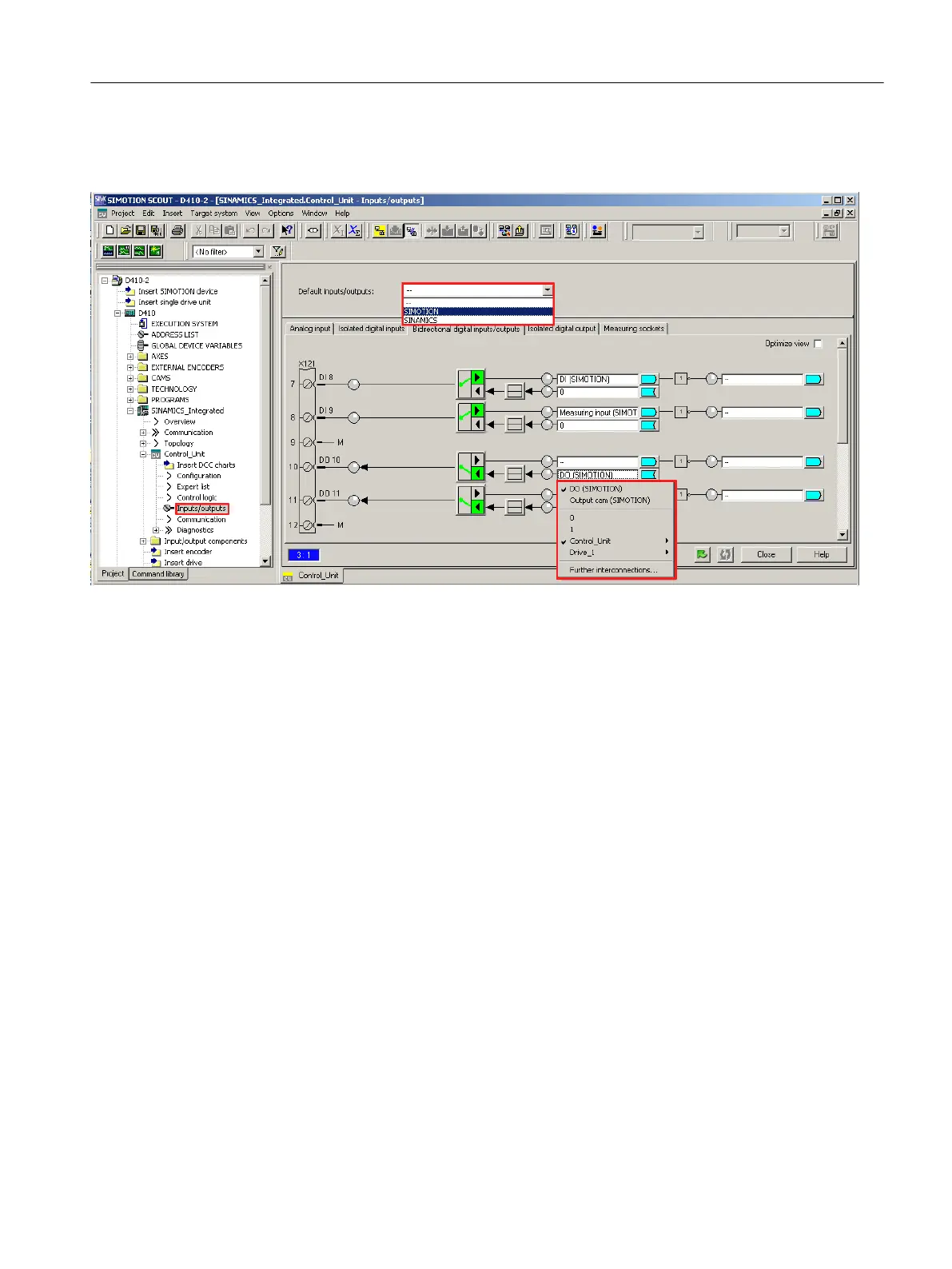
as a global measuring input input for SIMOTION with "Measuring input (SIMOTION)"
● Used as an output cam output for SIMOTION with "output cam (SIMOTION)"
Figure 7-32 Configuration of D410-2 I/Os (terminal X121)
24 V supply for DO
If no digital outputs are used, the SIMOTION D410-2 can be supplied via the Power Module.
A
24 V supply must be connected to terminal X124 for the digital outputs to be used. If a digital
output is parameterized and the 24 V supply is not connected (or the level is too low), alarm
A03506 is issued on the SINAMICS side (can also be parameterized as a fault).
Data transfer
If the D410‑2 onboard I/Os are interconnected using symbols (or if telegram 39x is used for
the onboard I/Os), the status information of the DI and DO will be transmitted to cu.p2048 at
the PROFIdrive PZD sampling rate. Sampling of the inputs and outputs is also performed in
the sampling time parameterized according to cu.p0799.
The same applies if the I/Os are manually interconnected to a drive telegram via a BICO
converter.
Transfer of the output values and feedback of the input values is therefore subject to dead
times and jitter.
For time-critical applications, use of measuring probes or cams is recommended. Alternately,
the isochronous I/Os, I/Os of TM15, TM17, or isochronous ET 200 I/Os can be used.
Commissioning (software)
7.10 Configuring drive-related I/Os
SIMOTION D410-2
Commissioning and Hardware Installation Manual, 01/2015 209
 Loading...


