Equipotential bonding
A
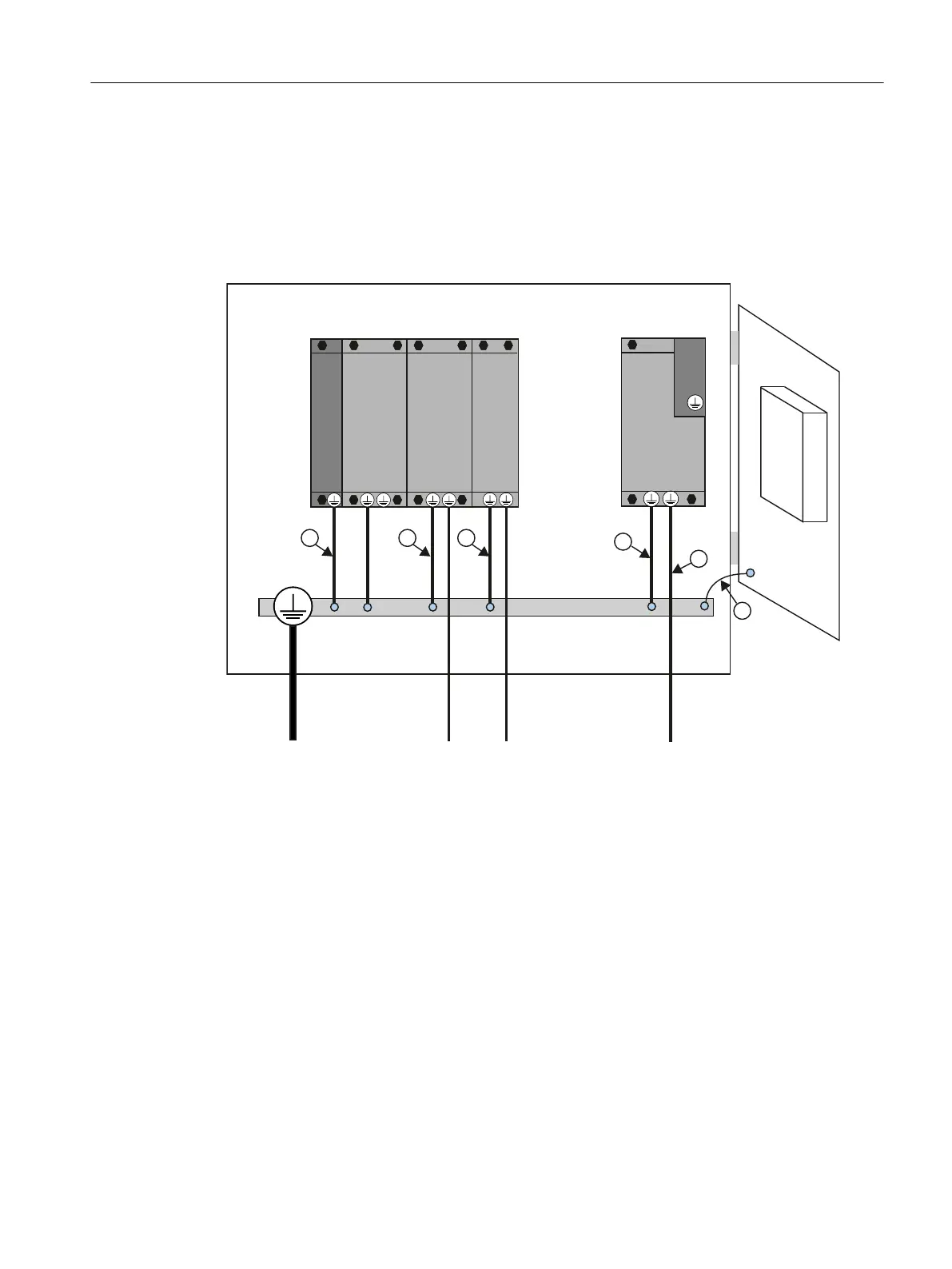
mounting plate serves simultaneously as an equipotential bonding surface. This means that
no additional equipotential bonding is required within the drive line-up. If a common bright
mounting plate is not available, then equally good equipotential bonding ⑨ must be
established using cable cross-sections as listed in the table above or, as a minimum, with the
same conductivity.
'RRU
&8/0000030
&8
+0,
6
%ORFNVL]H
6
%RRNVL]H
Figure 4-5 Protective conductor connection, cabinet without equipotential bonding surface
Communication links
Within the same control cabinet, no equipotential bonding conductor is required for fieldbus
components if they installed as described above.
You have to ensure equipotential bonding for communication connections between remote
components
in a system (e.g. devices in different control cabinets) as well as between buildings
or building sections.
If, for example, data cables (PROFIBUS, PROFINET, Ethernet or DRIVE‑CLiQ) are routed
through several control cabinets, equipotential bonding must be established with an
equipotential bonding conductor. Install the equipotential bonding conductor together with the
data cable.
The following minimum cross-sections are required according to IEC 60364-5-54:
● For copper, at least 6 mm²
● For aluminum, at least 16 mm²
● For steel, at least 50 mm²
Connecting
4.3 Protective conductor connection and potential equalization
SIMOTION D410-2
Commissioning and Hardware Installation Manual, 01/2015 53
 Loading...


