Configuration/programming
2.2 Configuring and programming TM1x modules
TM15 / TM17 High Feature Operating Manual
24 Commissioning Manual, 05/2009
Table 2- 2 "Function" column: Options in the drop-down menu
Menu option Description
DI Channel used as a digital input
DO (standard output
1
) Channel used as:
- Digital output, or
- Output of the output cam (without high switching accuracy)
Measuring input Channel used as an input of a measuring input
Output cam (fast output
2
) Channel used as a fast output of output cam (with high switching
accuracy)
1
The output of the output cam is calculated by the SIMOTION technology object in the IPO
cycle clock or position control cycle clock. (That is, the resolution is one IPO cycle clock or
one position control cycle clock.)
2
The switching instant of the output of the output cam is calculated by the TM15. For this
reason, the resolution is less than the position control cycle clock.
The value in the "Offset" column will later be added to the module address when the
technology object is configured. The result will be the absolute address of the respective I/O
channel.
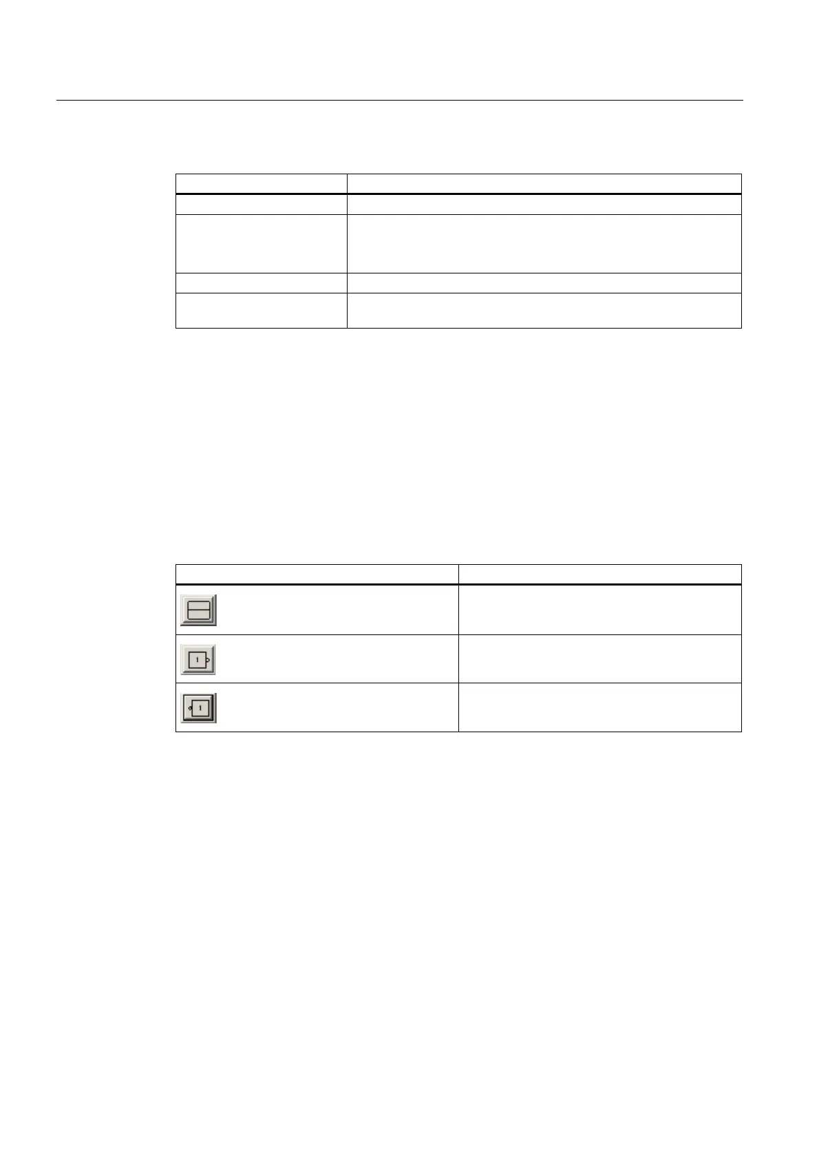
Depending on which function has been selected, you can switch between the input or output
using the symbol displayed under "Inverter".
Table 2- 3 "Inverter" column: Description of symbols
Symbol Description
Signal not inverted
Inverted input
Inverted output
 Loading...


