Basic Information about the Drive System
BICO technology: interconnection of signals
7-240
E Siemens AG, 2004. All rights reserved
SINAMICS S120 Installation and Start-Up Manual, 12/04 Edition
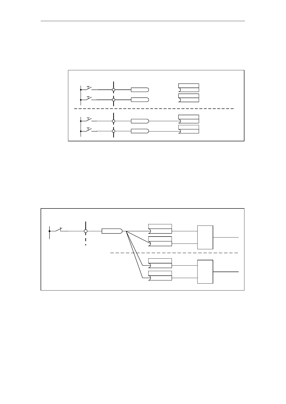
Example 1: Interconnection of digital signals
Suppose you want to operate a drive via terminals DI 0 and DI 1 on the Control
Unit using jog 1 and jog 2.
bico_3.vsd
BO: binector output
Signal source
BI: binector output
Signal sink
r0722.0
r0722.1
DI 1X122.2
DI 0X122.1
p1055.C
p1056.C
Jog 1
Jog 2
24 V
r0722.0
r0722.1
DI 1X122.2
DI 0X122.1
p1055.C
722.0
p1056.C
722.1
Jog 1
Jog 2
24 V
Internal
Internal
Fig. 7-7 Interconnection of digital signals (example)
Example 2: Connection of OC/OFF3 to several drives
The OFF3 signal is to be connected to two drives via terminal DI 2 on the Control
Unit.
Each drive has a binector input 1. OFF3 and 2. OFF3. The two signals are pro-
cessed via an AND gate to STW1.2 (OFF3).
bico_4.vsd
BO: binector output
Signal source
BI: binector input
Signal sink
r0722.2
DI 2X122.3
24 V
p0848.C
722.2
p0849.C
722.2
1. OFF3
&
2. OFF3
OFF3
Drive 1
p0848.C
722.2
p0849.C
722.2
1. OFF3
&
2. OFF3
OFF3
Drive 2
Fig. 7-8 Connection of OFF3 to several drives (example)

 Loading...


