Programming
10.6 Tool and tool offset
Cylindrical grinding
298 Programming and Operating Manual, 07/2009, 6FC5398-4CP10-2BA0
10.6.8 Example of tool radius compensation
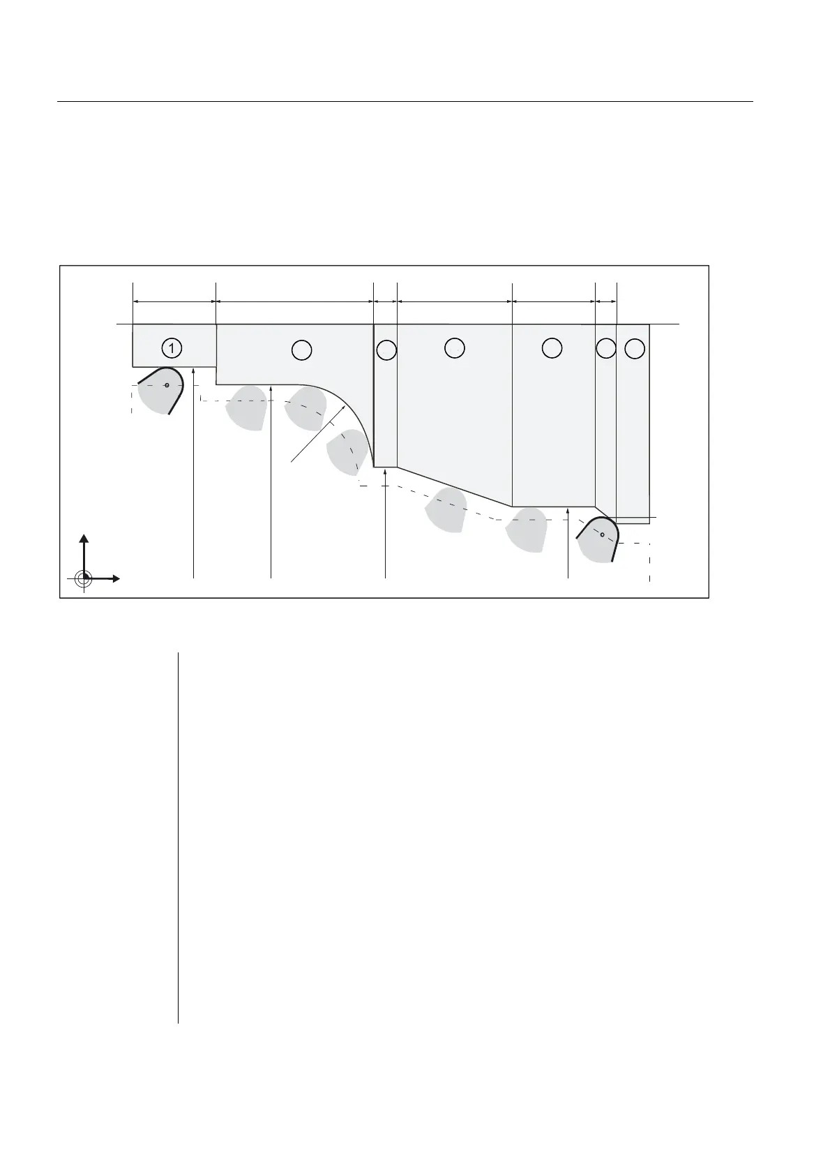
The wheel should have the contour shown in the figure. Dressing takes place from left to
right using MIRROR and G41
Caution: The workpiece zero (XWP) in wheel data must be -110 to be able to program the
contour in workpiece coordinates.
S
S
S
S
;
=
r
5
5
5
5
5
Figure 10-34 Example for contour dressing
N1 ; Contour cut
N10 DIAMON F... S... M... ; Radius dimension, technological values
N15 G500 ; Work offset "OFF"
N20 MIRROR X0 Z0 ; Begin compensation mode
N30 G90 G0 X-90
N40 Z-10
N50 X110 ; Approach R55
N60 G41 G64 G1 Z20 F500 ; Dressing contour section ①
N70 X100
N80 Z60 RND=20 ; Dressing contour section ①
N90 X60
N100 Z68 ; Dressing contour section ①
N110 X40 Z98 ; Dressing contour section ①
N120 Z118 ; Dressing contour section ①
N130 X30 Z123 ; Dressing contour section ①
N140 Z123 ; Dressing contour section ①
N150 G0 X-90 ;Move clear
N160 MIRROR ; End compensation mode
M17