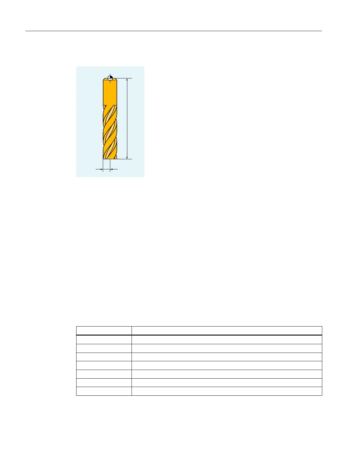
Tool geometry variables (length, radius)
T Tool carrier reference point
R Tool radius
L Tool length
The tool geometry variables consist of several components (geometry, wear). The control
computes the components to a resulting size (e.g. total length 1, total radius). The relevant
overall dimension becomes operative when the offset memory is activated.
How these values are calculated in the axes is determined by the tool type and the current plane
(G17/G18/G19).
2.5.5 Tool types
2.5.5.1 Tool type number and tool groups
Each tool type is assigned a unique 3-digit number. The assignment of the tool to one of the
following technologies or tool groups is realized using the first digit (the hundreds position):
Tool type Tool group
1xy Milling tools (Page 71)
2xy Drills (Page 73)
3xy Reserved
4xy Grinding tools (Page 74)
5xy Turning tools (Page 76)
6xy Reserved
7xy Special tools (Page 78)
Fundamentals
2.5 Tool offsets
NC programming
70 Programming Manual, 12/2019, 6FC5398-2EP40-0BA0

 Loading...


