EasyManuals Logo

Siemens SINUMERIK 840D sl Programming Manual

Siemens SINUMERIK 840D sl
1334 pages
To Next Page IconTo Next Page
To Previous Page IconTo Previous Page
Page #77 background imageLoading...
Page #77 background image
Tool parameters
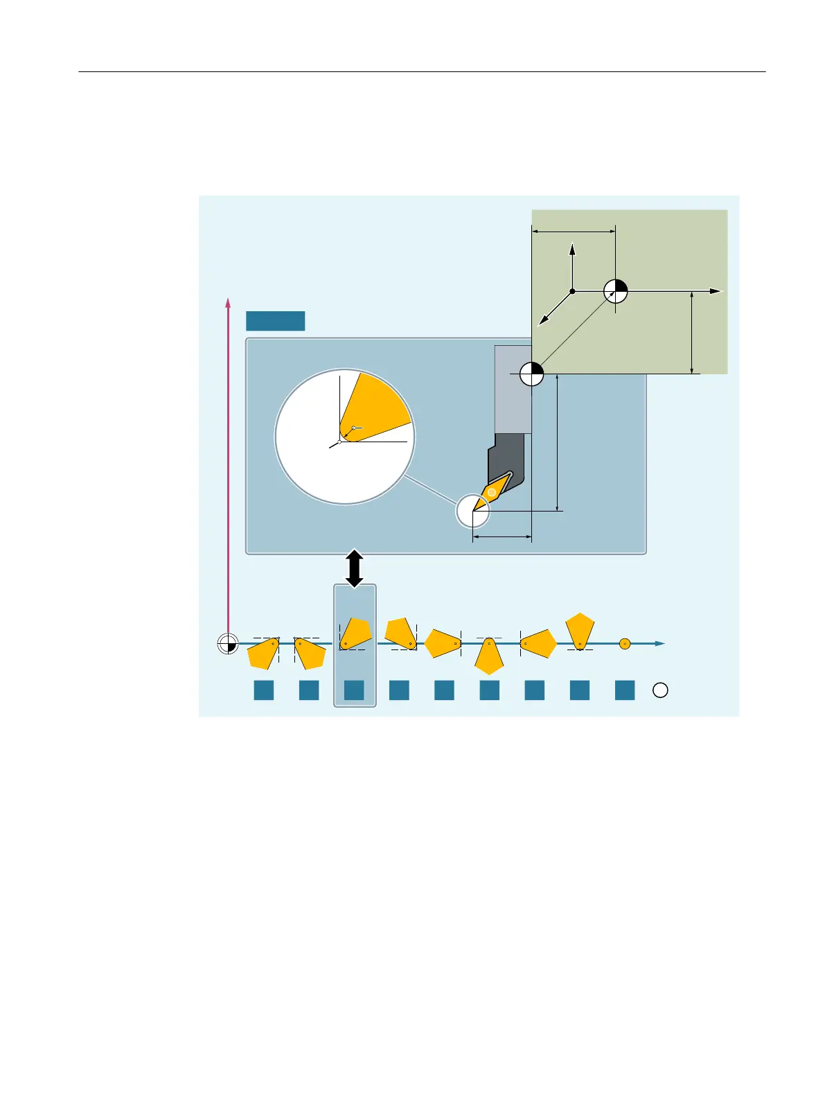
The following diagram provides an overview of which turning tool parameters are entered in the
compensation memory:
5
3
6
/
/
7
*;=
/
7
/
/
;
=
Cutting edge position (1 ... 9) for machining behind the turning center
P Tool tip
S Cutting edge center point
R Cutting edge radius
T Tool carrier reference point
T' Tool holder reference point
L1 Geometry - length 1
L2 Geometry - length 2
L1' Base dimension - length 1
L2' Base dimension - length 2
L3' Base dimension - length 3
Fundamentals
2.5 Tool offsets
NC programming
Programming Manual, 12/2019, 6FC5398-2EP40-0BA0 77

Table of Contents

Other manuals for Siemens SINUMERIK 840D sl

Questions and Answers:

Question and Answer IconNeed help?

Do you have a question about the Siemens SINUMERIK 840D sl and is the answer not in the manual?

Siemens SINUMERIK 840D sl Specifications

General IconGeneral
Control TypeCNC
Number of AxesUp to 31
Max Number of Channels10
InterfacesEthernet, PROFIBUS, PROFINET, USB
Interpolation5-axis interpolation
Operating Temperature0°C to 45°C
Relative HumidityUp to 95% (non-condensing)
DisplayTFT color display, various sizes
Programming LanguagesDIN/ISO
Safety FeaturesSafety Integrated
PLCIntegrated PLC S7-300
Drive InterfaceSINAMICS S120
Data StorageCF card, USB
Operating SystemWindows-based

Related product manuals