EasyManuals Logo

Siemens SINUMERIK 840D sl Programming Manual

Siemens SINUMERIK 840D sl
1334 pages
To Next Page IconTo Next Page
To Previous Page IconTo Previous Page
Page #79 background imageLoading...
Page #79 background image
Tool parameters
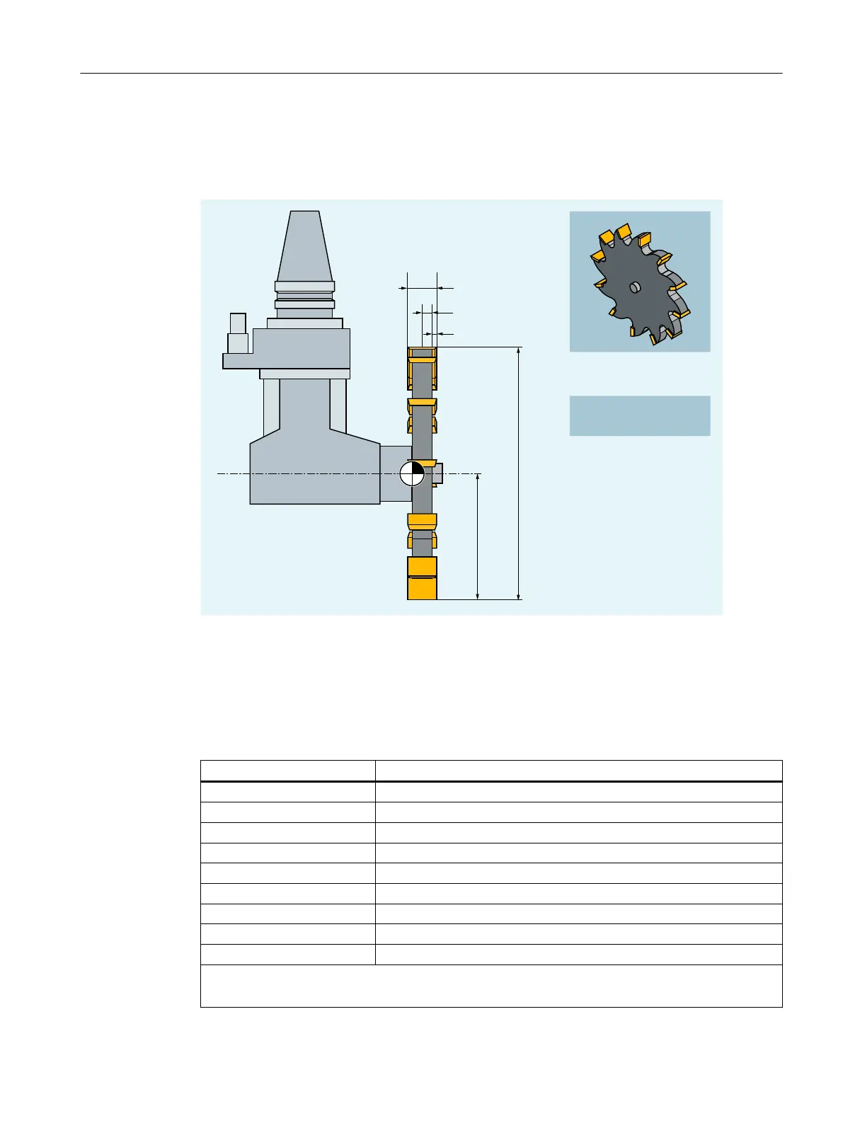
The following diagram provides an overview of which tool parameters for "Slotting saw" tool
type are entered in the compensation memory:
7
E
/
N
G
/
/ G
/ EN
T' Tool carrier reference point
L1 Geometry - length 1
L2 Geometry - length 2
d Diameter
b Slot width
k Projection
Tool parameters Meaning
$TC_DP1 Tool type
$TC_DP3 Geometry - length 1
$TC_DP4 Geometry - length 2
$TC_DP6 Diameter
$TC_DP7 Slot width
$TC_DP8 Projection
$TC_DP21 Base dimension length 1
$TC_DP22 Base dimension length 2
$TC_DP23 Base dimension length 3
Wear values corresponding to the requirements.
Other values should be set to 0.
Fundamentals
2.5 Tool offsets
NC programming
Programming Manual, 12/2019, 6FC5398-2EP40-0BA0 79

Table of Contents

Other manuals for Siemens SINUMERIK 840D sl

Questions and Answers:

Question and Answer IconNeed help?

Do you have a question about the Siemens SINUMERIK 840D sl and is the answer not in the manual?

Siemens SINUMERIK 840D sl Specifications

General IconGeneral
Control TypeCNC
Number of AxesUp to 31
Max Number of Channels10
InterfacesEthernet, PROFIBUS, PROFINET, USB
Interpolation5-axis interpolation
Operating Temperature0°C to 45°C
Relative HumidityUp to 95% (non-condensing)
DisplayTFT color display, various sizes
Programming LanguagesDIN/ISO
Safety FeaturesSafety Integrated
PLCIntegrated PLC S7-300
Drive InterfaceSINAMICS S120
Data StorageCF card, USB
Operating SystemWindows-based

Related product manuals