Detailed description
2.6 Interface structure
Basic logic functions: PLC basic program solution line (P3 sl)
Function Manual, 11/2006, 6FC5397-0BP10-2BA0
33
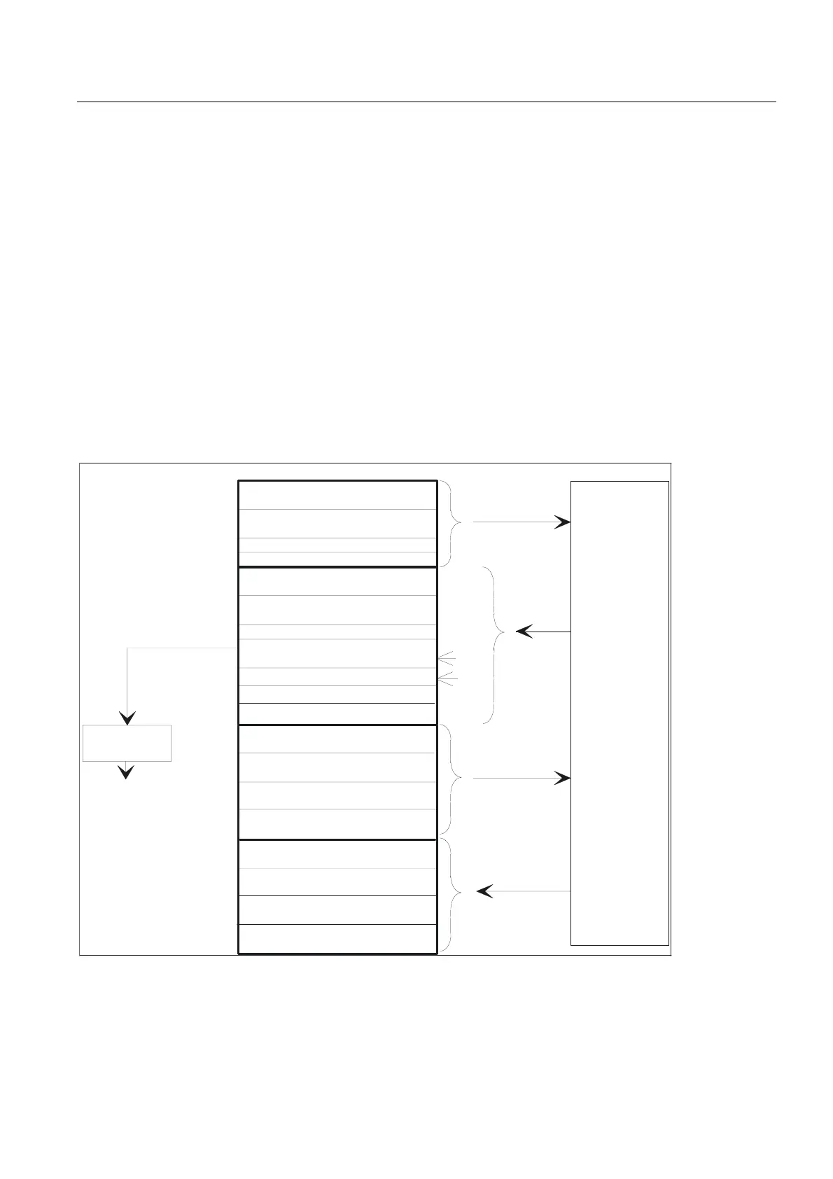
Compile-cycle signals
In addition to the standard signals exchanged between the PLC and NCK, an interface data
block for compile cycles is also generated if required (DB9). The associated signals, which
are dependent on the compile cycles, are transmitted cyclically at the start of OB1. The basic
program starts transmission at the lowest address and works up to the highest. First, signals
are transferred from the PLC to the NCK, then from the NCK to the PLC. The user must
synchronize the NCK and PLC as necessary (e.g. using the semaphore technique). Signal
transmission is asynchronous between NCK and PLC. This means, for example, that active
NCK data transmission can be interrupted by the PLC. This can mean that data is not always
consistent.
PLC/NCK signals
The group of signals from the PLC to NCK includes:
• Signals for modifying the digital and analog I/O signals of the NCK
• Keyswitch and emergency stop signals
&RQWURORIGLJLWDO1&.RXWSXWV
%\WH
'%
&RQWURORIGLJLWDO1&.LQSXWV
RQERDUGLQSXWV
RQERDUGRXWSXWV
$[LVWDEOHV
.H\VZLWFKHPHUJHQF\6723
$FWXDOYDOXHVIRUGLJLWDO1&.LQSXWV
RQERDUGLQSXWV
6HWSRLQWVIRUGLJLWDO1&.RXWSXWV
RQERDUGRXWSXWV
9DULRXVVLJQDOV
6WDWXVVLJQDOV
1&.
+DQGZKHHOVHOHFWLRQ
+0,VWDWXVVLJQDOV
%DVLFSURJUDPVWDWXVVLJQDOV
+0,
%3
'HFRGLQJ
+DQGZKHHO
VHOHFWLRQ
$[LVLQWHUIDFH
*HRD[LVLQWHUIDFH
LQFKDQQHO
&RQWURORIGLJLWDO1&.LQSXWV
H[WHUQDOLQSXWV
&RQWURORIGLJLWDO1&.RXWSXWV
H[WHUQDORXWSXWV
$FWXDOYDOXHVIRUGLJLWDO1&.LQSXWV
H[WHUQDOLQSXWV
6HWSRLQWVIRUGLJLWDO1&.RXWSXWV
H[WHUQDORXWSXWV
&RQWURORIDQDORJ1&.LQSXWV
H[WHUQDOLQSXWV
&RQWURORIDQDORJ1&.RXWSXWV
H[WHUQDORXWSXWV
$FWXDOYDOXHVIRUDQDORJ1&.LQSXWV
H[WHUQDOLQSXWV
6HWSRLQWVIRUDQDORJ1&.RXWSXWV
H[WHUQDORXWSXWV
6RIWZDUHFDP
Figure 2-5 PLC/NCK interface

 Loading...


