EasyManuals Logo

Siemens SINUMERIK 840D Function Manual

Siemens SINUMERIK 840D
2184 pages
To Next Page IconTo Next Page
To Previous Page IconTo Previous Page
Page #1829 background imageLoading...
Page #1829 background image
Detailed Description
2.3 Tool cutting edge
Basic logic functions: Tool Offset (W1)
Function Manual, 11/2006, 6FC5397-0BP10-2BA0
41
Length of cutting edge
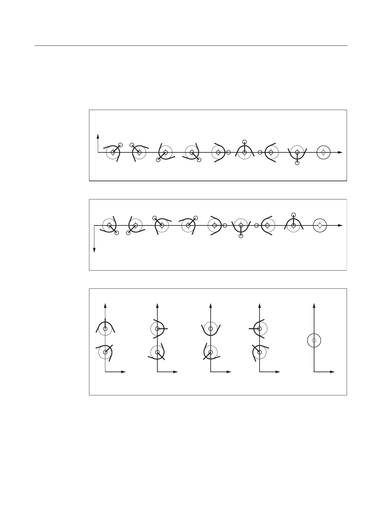
The cutting edge position describes the position of the tool tip P in relation to the cutting
edge center point S. The cutting edge position is entered in tool parameter 2 (shown as P2 in
the figure).
3  3  3 3  3  3  3 
3 6
3 3 
;
=
3
6
Figure 2-6 Tool parameter 2 (P2): Machining behind the turning center
3  3  3 3  3  3  3 
3 6
3 3 
;
=
3
6
Figure 2-7 Tool parameter 2 (P2): Machining in front of the turning center
;
=
3  3 
3 
3  3 
3  3 
3 6
3 
3 
3
6
;
=
;
=
;
=
;
=
Figure 2-8 Tool parameter 2 (P2): Cutting edge position for vertical boring and turning mills

Table of Contents

Other manuals for Siemens SINUMERIK 840D

Questions and Answers:

Question and Answer IconNeed help?

Do you have a question about the Siemens SINUMERIK 840D and is the answer not in the manual?

Siemens SINUMERIK 840D Specifications

General IconGeneral
SeriesSINUMERIK 840D
AxesUp to 31
ChannelsUp to 10
Operating SystemWindows-based
Power Supply24 V DC
Control Unit TypeCNC
InterfaceEthernet, PROFIBUS
DisplayTFT color display
InterpolationSpline
PLCIntegrated PLC
Data StorageCompactFlash, USB

Related product manuals