Detailed description
2.3 Setpoint /actual-value system
Basic logic functions: Velocities, Setpoint/Actual Value Systems, Closed-Loop Control (G2)
48 Function Manual, 11/2006, 6FC5397-0BP10-2BA0
Q
W>V@
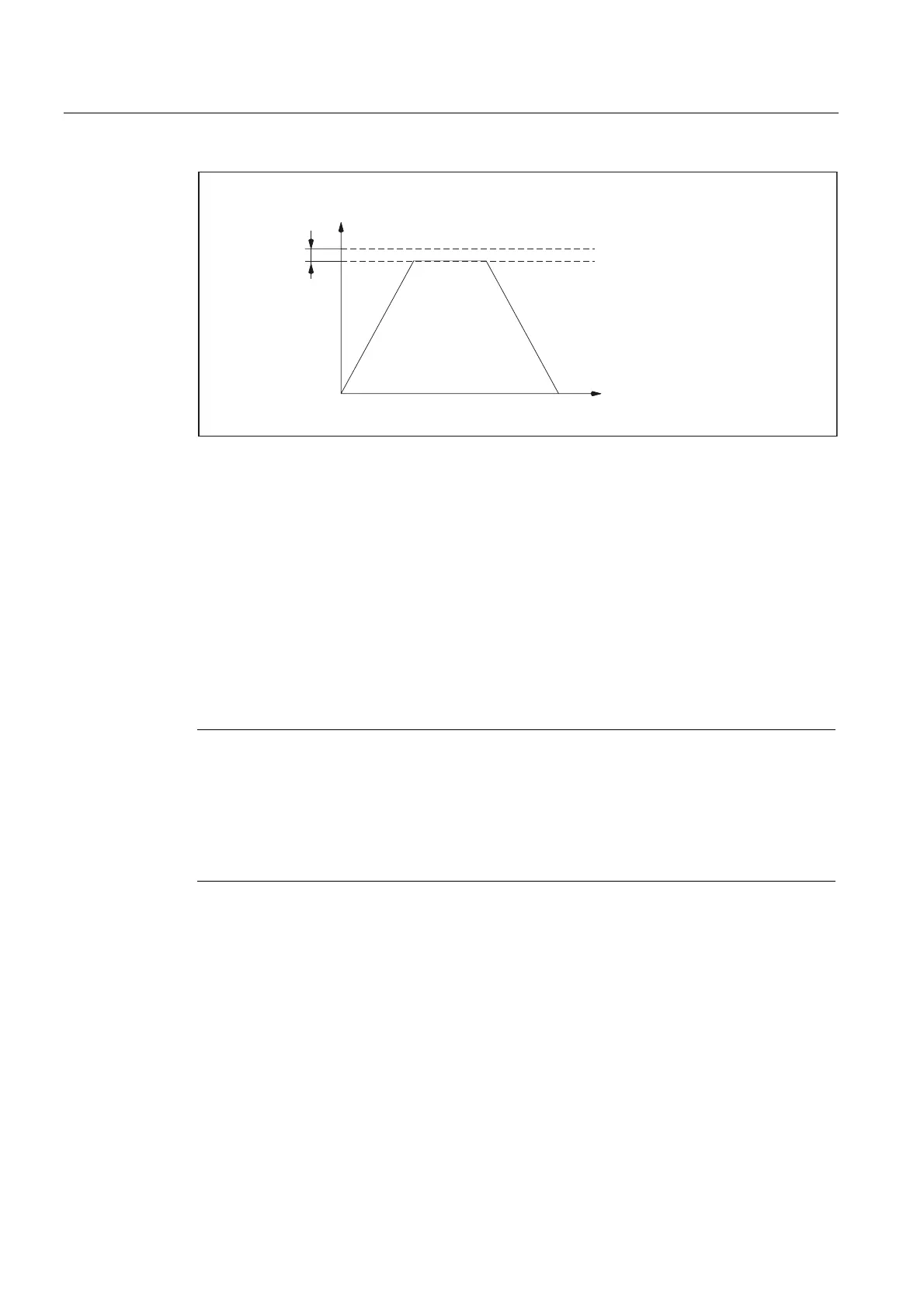
0'&75/287B/,0,7
0'0$;B$;B9(/2
0D[D[LVYHORFLW\
6SHHGVHWSRLQW
6HW
0D[VSHHGVHWSRLQW
Figure 2-5 Maximum speed setpoint
However, due to control processes, the axes should not reach their maximum velocity
(MD32000 $MA_MAX_AX_VELO) at 100% of the speed setpoint, but at 80% to 95%.
For axes, which reach their maximum velocity at around 80% of the speed setpoint range,
the default setting (80%) of machine data:
MD32000 $MA_MAX_AX_VELO (maximum axis velocity)
should be applied.
With SINUMERIK 840D/810, machine data:
MD36210 $MA_CTRLOUT_LIMIT[n] (maximum speed setpoint)
and
MD1405/2405 $MD_MOTOR_SPEED_LIMIT (motor monitoring speed)
must agree.
Note
For more information about setpoint adjustment for SIMODRIVE digital drives, see:
References:
/IAD/Installation & Startup Guide; "Axes and Spindles".
For more information about setpoint scaling for SIMODRIVE analog drives, see:
References:
/FB3/ Function Manual, Special Functions; Analog Axis (TE2).

 Loading...


