2
10.04 Operation
2.13 Tools and tool offsets
2
Siemens AG, 2004. All rights reserved
SINUMERIK 840D/840Di/810D Operation/Programming ShopMill (BAS) – 10.04 Edition 2-147
2.13.6 Tool offsets
Why use tool offsets?
You do not have to take tool diameters and lengths into account when
writing machining programs.
You can program workpiece dimensions directly, e.g. as specified in
the production drawing.
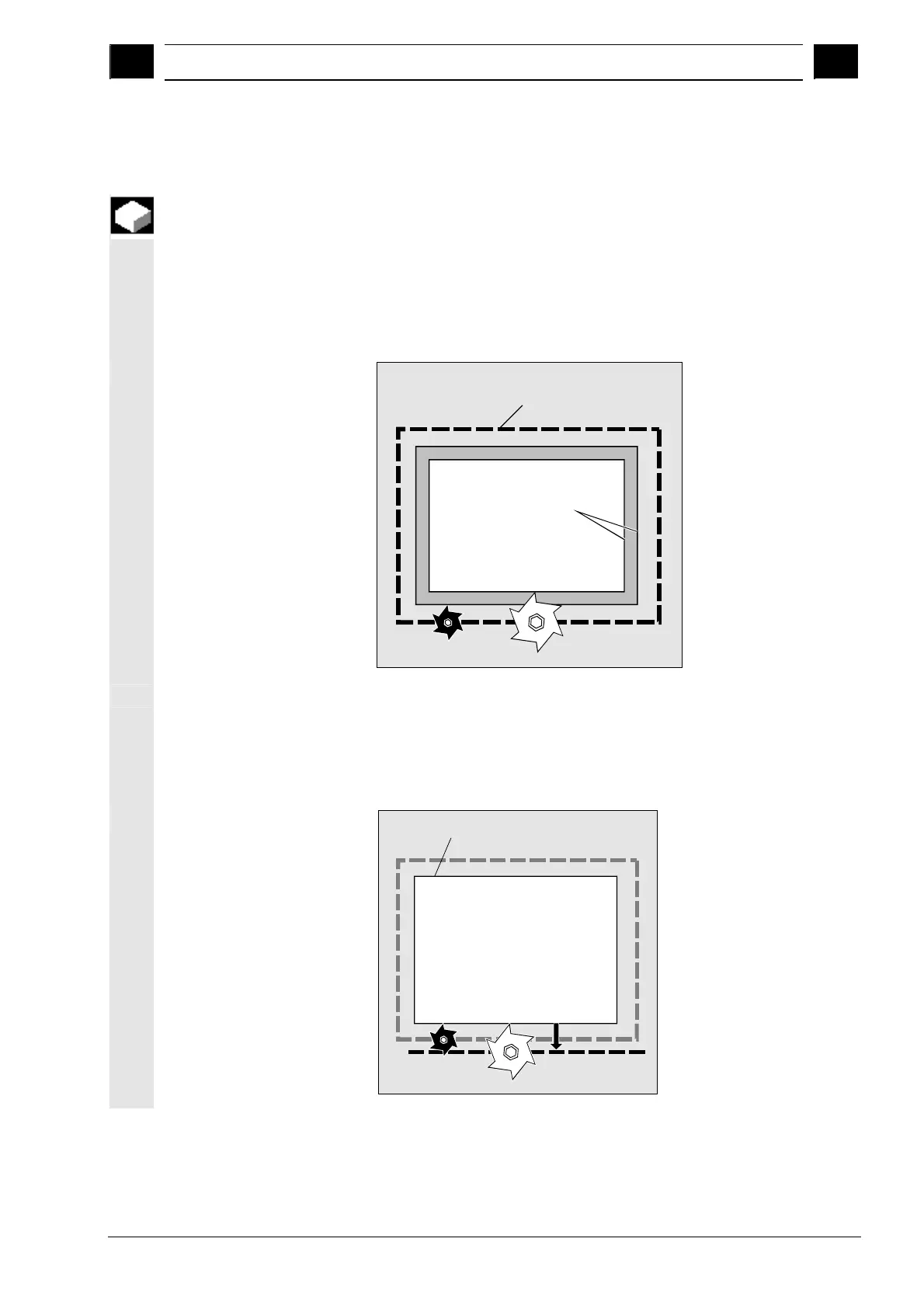
When machining a workpiece, the tool paths are controlled according
to the tool geometry such that the programmed contour can be
machined using any tool.
Tool path
Contour
The control corrects
the travel path
Enter the tool data separately in the "Tool list" and "Tool wear" tables.
When writing the program, you only need to call the tool you require.
While the program is being processed, the control fetches the offset
data it requires from the tool table and corrects the tool path
individually for different tools.
Corrected
tool path
Programmed contour

 Loading...


