Configuration
5-257SA522 Manual
C53000-G1176-C119-2
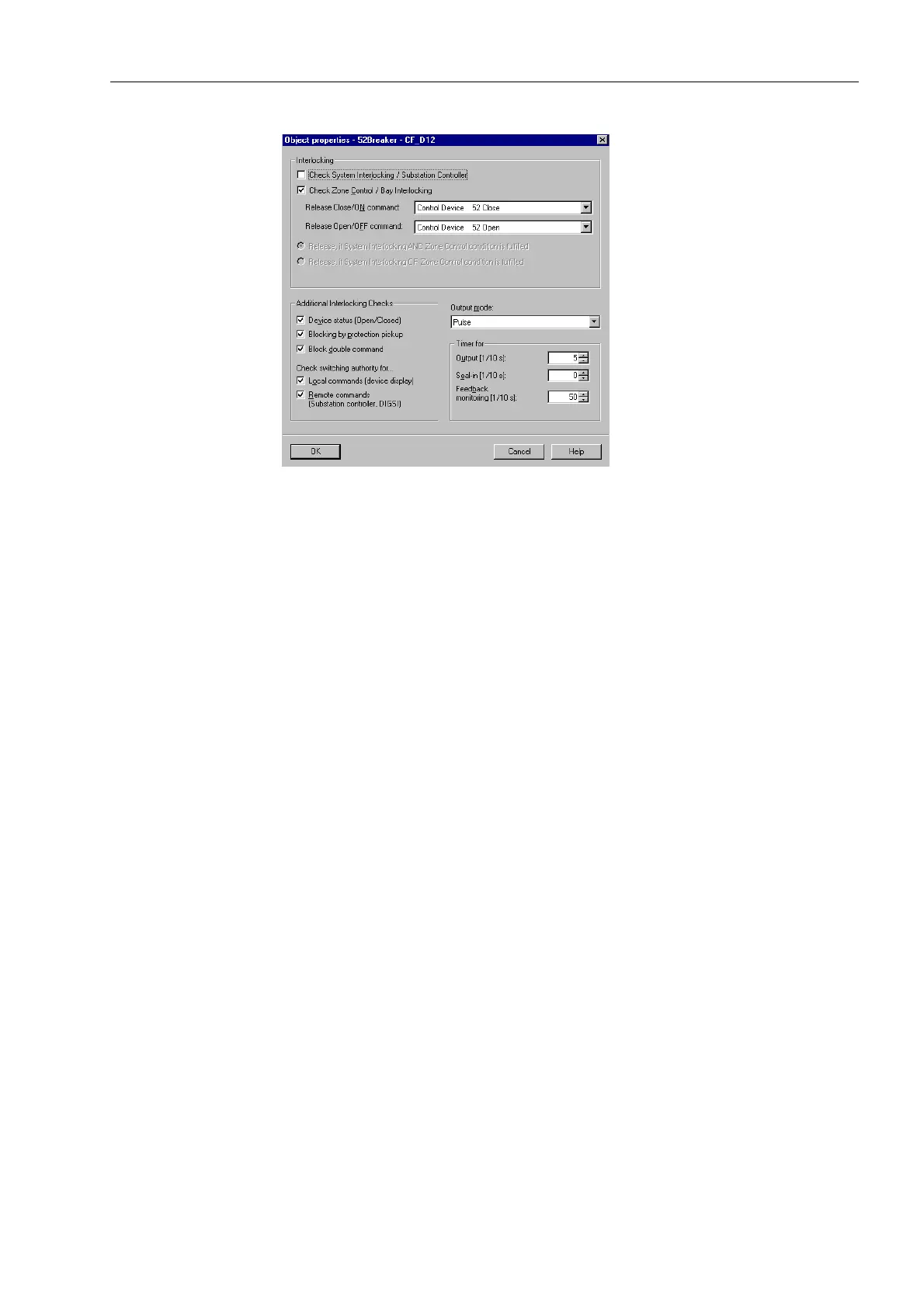
Figure 5-24 Dialogue box: object properties for a command with feedback
The conditional checks that should be conducted before execution of a switching com-
mand can also be defined:
• Device position (scheduled/actual): The switching command is ignored and a cor-
responding indication is issued if the switching device is already in the intended po-
sition. If this check is activated, switching direction control occurs not only for inter-
locked, but also for non-interlocked switching.
• Zone controlled (Bay Specific Interlocking): Logic functions created with CFC in the
relay are processed for interlocked switching.
• Blocked by protection: CLOSE commands to the switchgear are blocked as soon
as one of the protective functions or elements in the relay picks up. OPEN com-
mands, in contrast, can always be executed.
• Double operation: Parallel switching operations are blocked with respect to each
other: while one switching operation is being conducted, a second one cannot be
performed.
• Switching Authority – Local Commands: A local control switching command is only
allowed if local control is enabled on the relay (via lockswitch or setting).
• Switching Authority – Remote Commands: A remote control switching command is
only allowed if remote control is enabled on the relay (via lockswitch or setting).
Configuring a LED
Display as a Desti-
nation
Single point indications (SP), output indications (OUT), and internal single point indi-
cations (IntSP) may be assigned to LEDs. When this is done, you may select whether
the indications are to be latched (/) or unlatched (8).
Up to ten (10) indications may be assigned to a LED display. One indication may be
assigned to a maximum of ten (10) outputs (LEDs and output relays).
Configuring an
Indication Buffer
as a Destination
Dependent on the type and version of a relay, a maximum of three indication buffers
may be available for messages: Operation (Event Log) Buffer (2), and Fault (Trip Log)
Buffer (7). The indications from protective functions are firmly assigned to these indi-
cation buffers. For the others, Table 5-2 provides an overview of which indication type
may be configured to which buffer.

 Loading...


