Functions
6-97SA522 Manual
C53000-G1176-C119-2
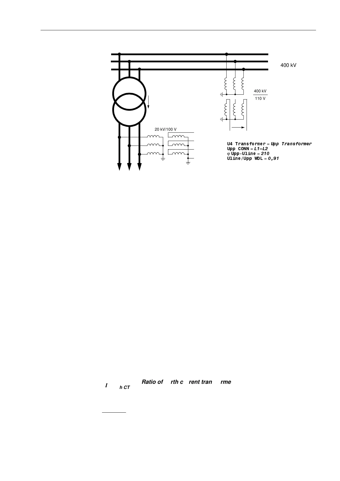
Figure 6-9 Busbar voltage, measured across a transformer
• Connection of the U
4
input to any other voltage signal U
X
, which may be processed
by the overvoltage protection function, refer to Appendix A, Figure 1-15:
Address is then set: 8WUDQVIRUPHU = 8[WUDQVIRUPHU.
It is assumed, that the U
x
transformer ratio is equal to the phase voltage transfomer
ratio
.
• If the U
4
input is not required, the following setting is applied:
Address 8WUDQVIRUPHU = 1RWFRQQHFWHG.
Also in this case the factor 8SK8GHOWD (Address , refer to the above) is
of importance, as it is utilised for the scaling of the measurement and disturbance
recording signals.
Current Trans-
former Connection
The device contains four current measurement inputs, three of which are connected
to the set of current transformers. The fourth current measuring input I
4
may be utilised
in various ways:
• Connection of the I
4
input to the earth current in the starpoint of the set of current
transformers on the protected feeder (normal connection, refer to Appendix A, Fig-
ure 1-9):
Address is then set to: ,WUDQVIRUPHU = ,QSURWOLQH and
Address to ,,SK&7 = 1.
• Connection of the I
4
input to a separate earth current transformer on the protected
feeder (e.g. a summation CT, refer to Appendix A, e.g. Figure 1-10).
Address is then set to: ,WUDQVIRUPHU = ,QSURWOLQH and
Address LVVHWWR,,SK&7:
Example:
L1
L2
L3
U
L1
U
L2
U
L3
(any voltage)
U
E
U
SS
feeder
Busbar
Yd5
220 kV
400 kV/220 kV
87UDQVIRUPHU
=
8SS7UDQVIRUPHU
8OLQH8SS:'/
=
8SS&211
=
/²/
ϕ
8SS8OLQH
=
°
220 kV/100 V
400 kV
110 V
400 kV
I
4
I
ph CT
⁄
Ratio of earth current transformer
Ratio of phase current transformers
------------------------------------------------------------------------------------------------------
=

 Loading...


