Functions
6-597SA522 Manual
C53000-G1176-C119-2
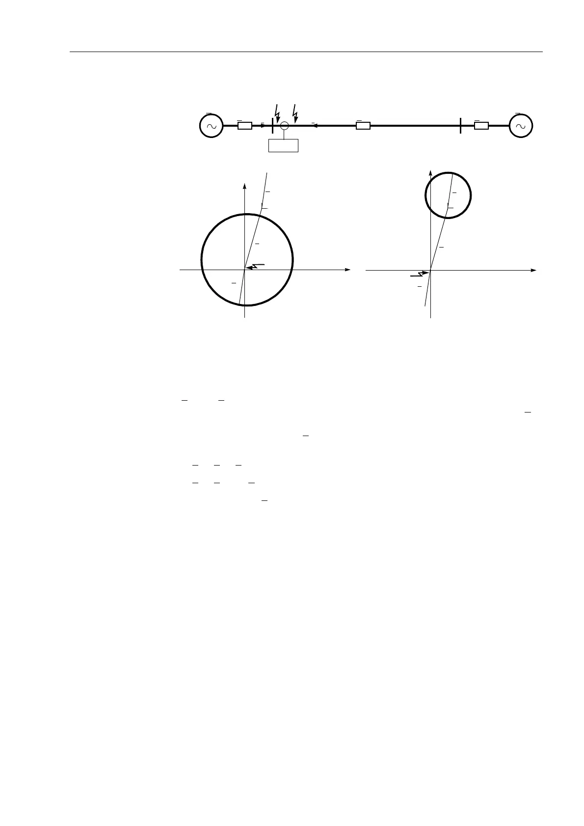
Figure 6-32 Polarized MHO circle with quadrature or memorized voltages
Assignment to the
Circles and
Zone Pick-up
The assignment of the loop impedances to the set characteristics of each distance
zones carried out as follows: For each zone the angle between two difference phasors
∆Z
1
and ∆Z
2
(Figure 6-33) is determined. These phasors result from the difference be-
tween the two zeniths of the circle diameter and the fault impedance. The zenith Z
r
corresponds to the set value for the zone under consideration (Z
r
and ϕ
Line
as shown
in Figure 6-30), the zenith k
· Z
S
corresponds to the polarizing magnitude. Therefore
the difference phasors are:
∆Z
1
= Z
F
– Z
r
∆Z
2
= Z
F
– k · Z
S
In the limiting case, Z
F
is located on the perimeter of the circle. In this case the angle
between the two difference phasors is 90° (Thales–theorem). Inside the circle the
angle is greater than 90° and outside the circle it is smaller than 90°.
F
2
F
1
E
1
E
2
Z
S1
Z
S2
Z
L
7SA522
R
jX
I
2
I
1
F
1
Z
S1
Z
L
6-32a
6-32c6-32b
Z
S2
R
jX
F
2
Z
S1
Z
L
Z
S2
Z
r
Z
r

 Loading...


