Functions
6-106 7SA522 Manual
C53000-G1176-C119-2
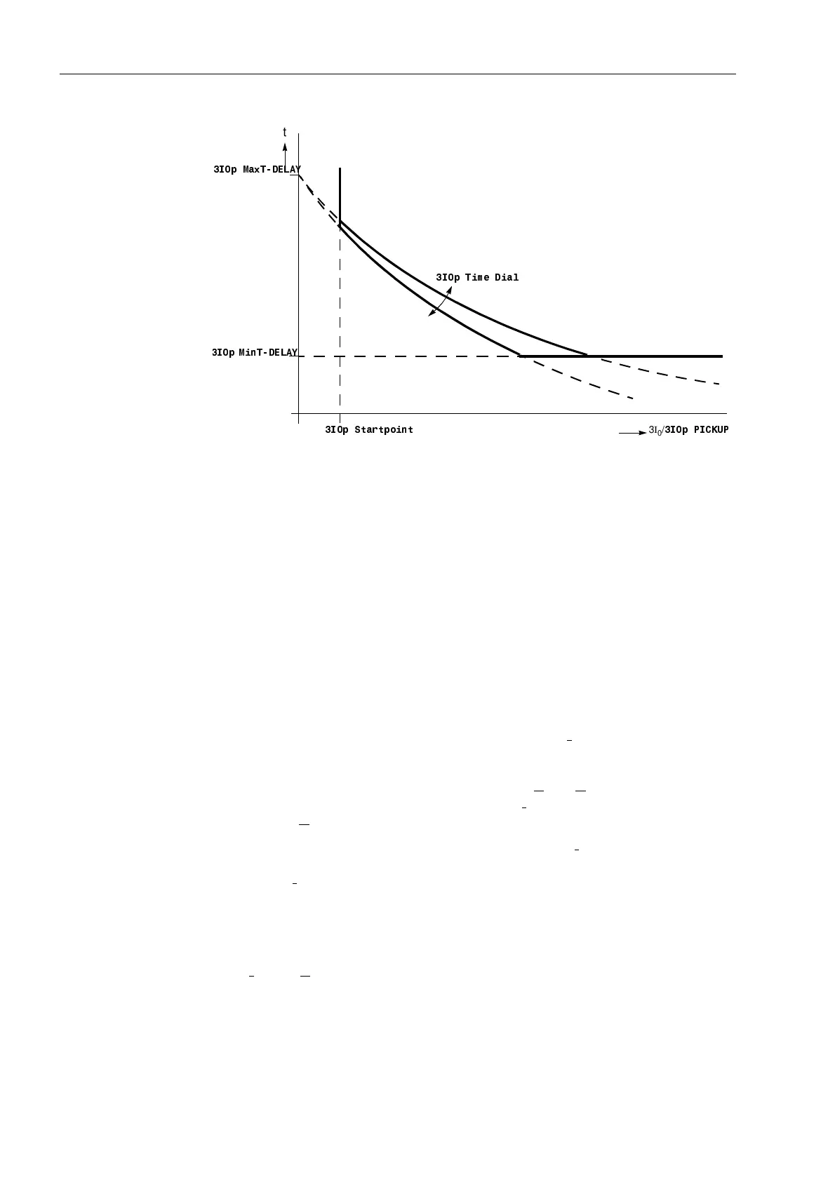
Figure 6-63 Setting parameter characteristics in the logarithmic–inverse curve
Direction
Determination
The direction of each required stage was already determined when setting the differ-
rent stages.
According to the requirements of the application, the directionality of each stage is in-
dividually selected. If for instance a directional earth fault protection with a non-direc-
tional back-up stage is required, this can be implemented by setting the 3I
0
>>–stage
directional with a short or no delay time and the 3I
0
>–stage with the same pick-up
threshold but a longer delay time as directional back-up stage. The 3I
0
>>>–stage
could be applied as an additional high set instantaneous stage.
If a stage is to operate with teleprotection according to Section 6.6, it may operate
without delay in conjunction with a permissive scheme. In the blocking scheme, a
short delay equal to the signal transmission time, plus a small reserve margin of ap-
prox. 20 ms is sufficient.
The direction is usually determined with the earth current I
E
= –3I
0
as the measured
value the angle of which is compared to a polarizing quantity (Sub-section 6.5.1). The
desired polarizing signal(s) is set in 32/$5,=$7,21 (address ). The presetting
ZLWK8RDQG,< generally also applies when only U
E
= 3U
0
is used as a polarizing
signal. If there is no transformer star-point current I
Y
connected to the device, auto-
matically only U
E
influences the direction determination.
If the direction determination must be carried out using only I
Y
as reference signal, the
setting ZLWK,<RQO\ is applied. This makes sense if a reliable transformer star-
point current I
Y
is always available at the device input I
4
. The direction determination
is then not affected by disturbances in the voltage transformer secondary circuits pro-
vided that the device is equipped with a normal sensitivity current input I
4
and the
transformer star-point current is connected to I
4 .
If direction determination must be carried out using the negative sequence system sig-
nals 3I
2
and 3U
2
the setting ZLWK8DQG, is applied. In this case, only the neg-
ative sequence system signals computed by the device are used for the direction de-
termination.
The position of the directional characteristic is determined with the setting parameters
'LU$/3+$ and 'LU%(7$ (addresses und ). As these set values are
0
1
,S0D[7'(/$<
3I
0
/
,S3,&.83
,S7LPH'LDO
,S0LQ7'(/$<
,S6WDUWSRLQW
t

 Loading...


