Control During Operation
7-37SA522 Manual
C53000-G1176-C119-2
LEDs that display a condition should light for as long as the condition is maintained.
The LED action is therefore generally not latched. Of course, these LEDs are also in-
cluded in the function check with the LED key .
Binary Outputs Indications can be configured to output relays for external indication (e.g. annunciator,
sequence-of-events recorder, RTU, etc), and operate like LEDs. See also Chapter 5
for details.
Front Panel To retrieve messages using the front panel:
First press the 0(18 key . The 0$,10(18 appears. The first menu item $QQXQ
FLDWLRQ) is marked.
All menus and message lists begin with a title. The number in the upper right corner
of the display indicates presently selected menu entry or message, and, behind the
slash, the total number of menu entries or messages (see Figure 7-1, each first line).
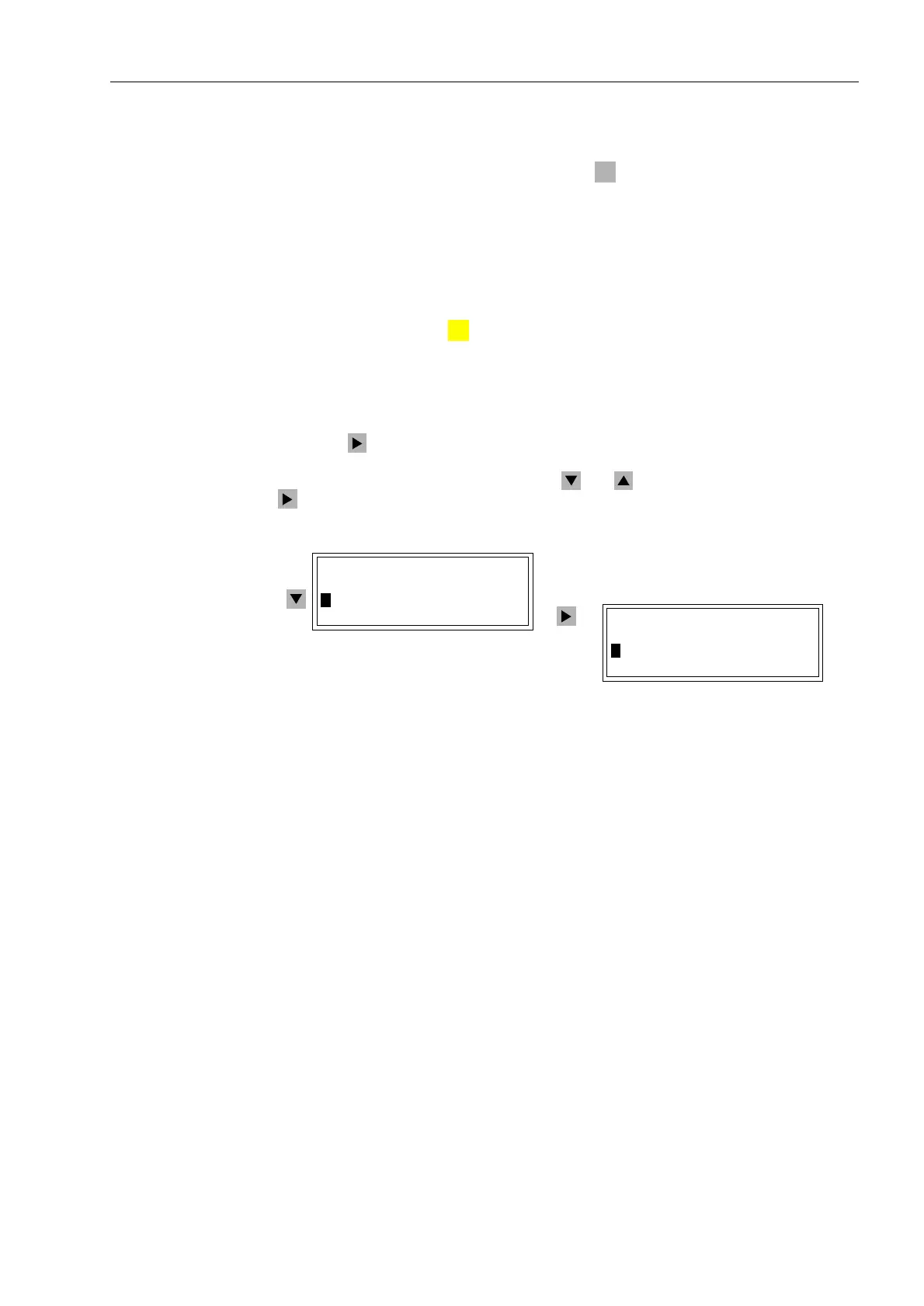
Press the key to go to the $1181&,$7,21 sub-menu, as shown in Figure 7-1. In
this menu the messages can be reached by entering the associated selection number,
or by selecting the desired entry using the and keys and moving further with the
key. This procedure is described in more detail below.
Figure 7-1 Selection of messages on the operator control panel
PC–Interfaces A personal computer running the program can be connected to the operating interface
on the front of the device to retrieve the messages. A PC can also be connected to the
service interface on the back of the device. This connection typically applies when the
PC is hard-wired with several devices, using a data bus (station computer) or modem.
Details about the operation of are contained in the “ Device Operation” handbook, or-
der no. E50417-H1176-C097.
LED
MENU
0$,10(18
!$QQXQFLDWLRQ²!
0HDVXUHPHQW²!
$1181&,$7,21
!(YHQW/RJ²!
7ULS/RJ²!

 Loading...


