Installation and Commissioning
8-16 7SA522 Manual
C53000-G1176-C119-2
For the device in the housing size
1
/
1
it is possible to change the contact of a particular
relay (R16 and R24) from normally open to normally closed (refer to general dia-
grams in the appendix under Section 1.2) on the input/output
modules I/O–1 without power supply ( in slot 19).
1
1
) Factory settings for devices with power supply voltages of 24 VDC to 125 VDC
2
) Factory settings for devices with power supply voltages of 110 VDC to 250 VDC and 115 VAC
3
) Factory settings for devices with power supply voltages of 220 VDC to 25 VDC and 115 VAC
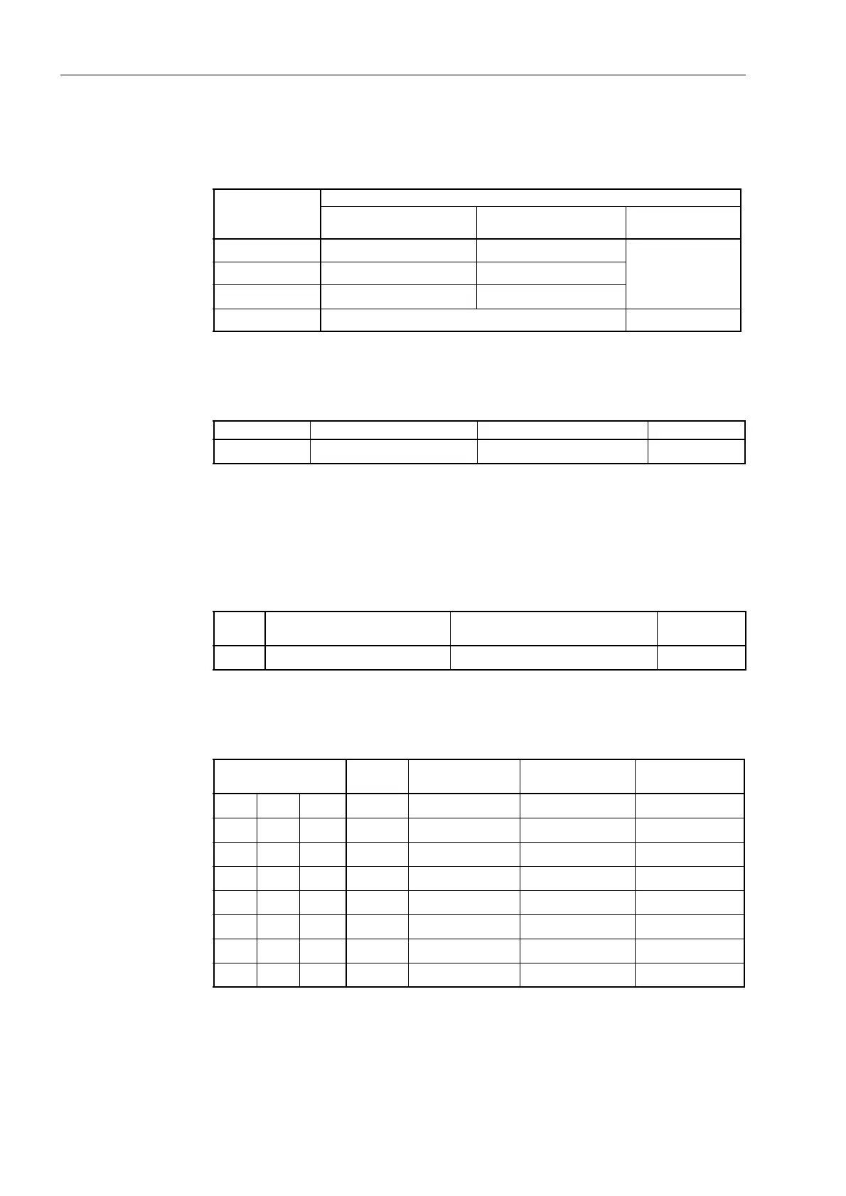
Table 8-2 Jumper settings for the nominal voltage of the integrated power supply on the
input/output board I/O–1
with power supply
Jumper Nominal voltage
DC 60/110/125 V DC 110/125/220/250 V
AC 115 V
DC 24/48 V
X51 1–2 2–3 Jumpers
X51 to X53
are not fitted
X52 1–2 and 3–4 2–3
X53 1–2 2–3
Can be interchanged Not changeable
Table 8-3 Jumper setting for the quiescent state of the life contact on the
input/output board I/O–1
with power supply
Jumper Open in the quiescent state Closed in the quiescent state Presetting
X40 1–2 2–3 2–3
Table 8-4 Jumper setting for the quiescent state of the output relay R16 or R24
Jumper Open in the quiescent state
(normally closed)
Closed in the quiescent state
(normally open)
Presetting
X40 1–2 2–3 1–2
Table 8-5 Jumper settings for the Pick-up Voltages of the binary inputs BI1 through BI8,
BI9 through BI16, and BI17 through BI24 on the input/output board I/O–1
Binary Inputs Jumper 17 VDC
Pick-up
1
)
73 VDC
Pick-up
2
)
154 VDC
Pick-up
3
)
BI1 BI9 BI17 X21/X22 L M H
BI2 BI10 BI18 X23/X24 L M H
BI3 BI11 BI19 X25/X26 L M H
BI4 BI12 BI20 X27/X28 L M H
BI5 BI13 BI21 X29/X30 L M H
BI6 BI14 BI22 X31/X32 L M H
BI7 BI15 BI23 X33/X34 L M H
BI8 BI16 BI24 X35/X36 L M H

 Loading...


