Functions
102
7SS52 V4 Manual
C53000-G1176-C182-1
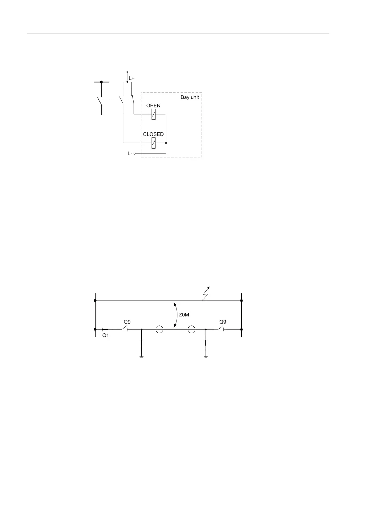
Figure 5-9, page 102 shows the basic connection scheme.
Figure 5-9 Isolator status indication
The isolator states of each feeder are indicated in the bay units 7SS523 by red or
green LEDs. The preselection can be seen in Table A-29, page 390.
The isolator replica of the entire plant can be visualized in graphic form using the
DIGSI Plant Visualization.
Recognition of the
feeder isolator sta-
tus
With parallel lines, due to the short-circuit current, a current can be induced in the
switched-off and earthed line, which is processed as differential current in the busbar
protection without Q9.(Figure 5-10, page 102). The protection sees a current in the
zero sequence system of the earthed feeder.
Integrating the feeder isolator (Q9) into the isolator logic prevents spurious tripping by
the 7SS52 V4.
Figure 5-10 Parallel feeders
The 7SS52 V4 is configured to identify an isolator automatically as a line isolator.
If an isolator is configured as line isolator, the feeder bay will only be allocated to a bus
zone if both the corresponding bus isolator and the feeder isolator are closed.

 Loading...


