Maintenance and Repair
298
7SS52 V4 Manual
C53000-G1176-C182-1
should be placed vertically on a conductive surface. Such a conductive surface
could be e.g. an EMC mat.
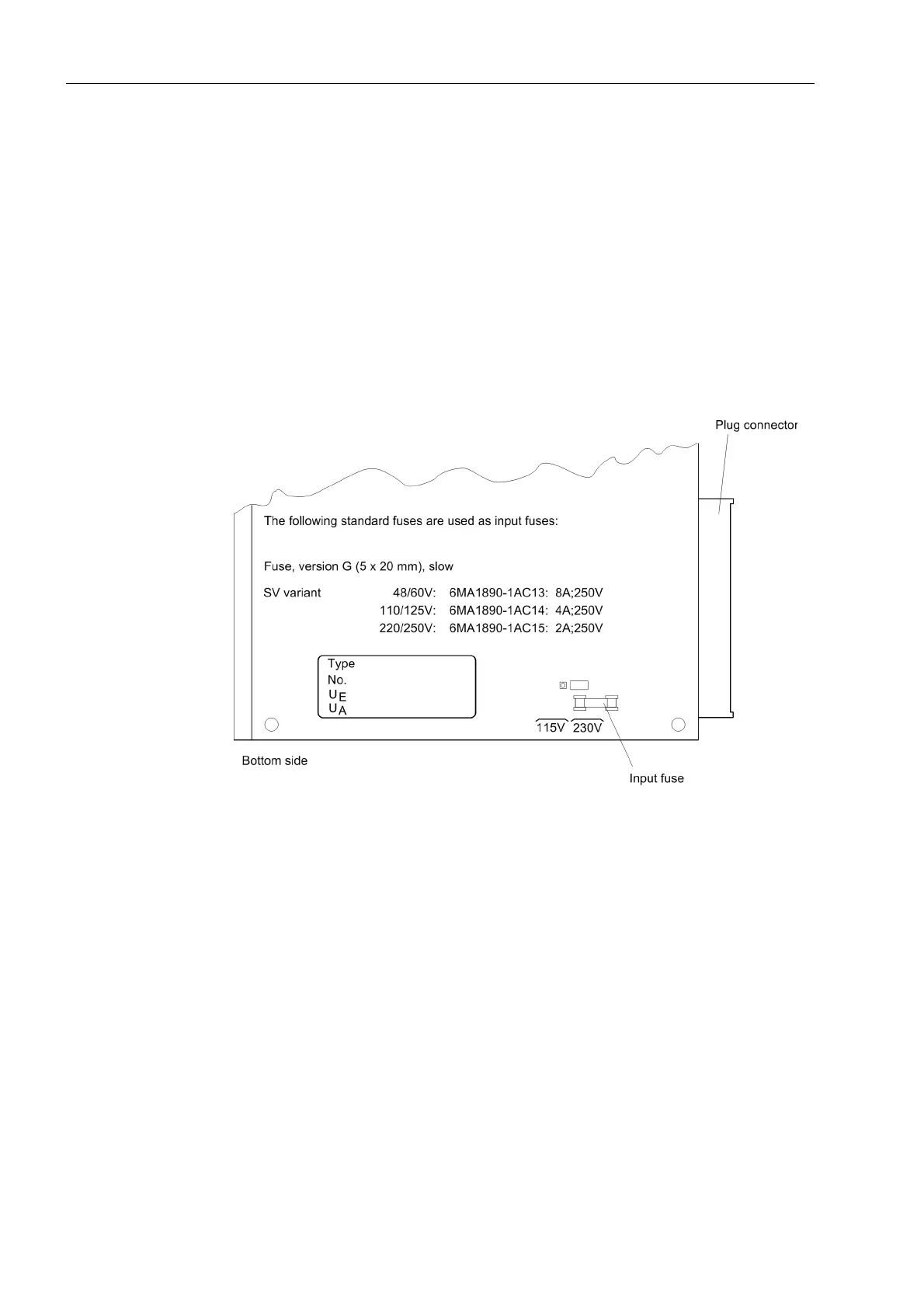
Replace the fine-wire fuse. The location of the fine-wire fuse can be seen in
Figure 8-8, page 298.
Insert the module again into the housing. Make sure that the module is fixed
correctly and firmly contacted with the rear-side plug connector.
Fasten the front panel again. Please note that the switch for the power supply SV
is not accessible with the front panel closed.
After fastening the front panel, switch the device on. If the auxiliary voltage failure
continues to be indicated, there must be a failure or short-circuit in the internal
power supply. The power supply module (SV) should be sent to the factory.
Figure 8-8 Location of the fine-wire fuse on the power supply module (SV) of the central unit
Bay unit To replace the fine-wire fuse in the bay unit:
Remove the covering caps on the front panel, and unscrew the screws.
Swing the front panel to the left (7SS523), or remove it (7SS525).
The fine-wire fuse is located on the power supply module (SAF or PFE/SVW). The
location of that module is shown in Figure 8-6, page 296 or Figure 8-7, page 296.
Pull off the front connector of the ribbon cable from the module.
Pull the module out of the housing. Use the extraction handle (included in the
delivery) to loosen the module.
To avoid electrostatic discharge through components, the withdrawn modules
should be placed vertically on a conductive surface. Such a conductive surface
could be e.g. an EMC mat.
Replace the fine-wire fuse. The location of the fine-wire fuse can be seen in
Figure 8-9, page 299 or Figure A-11, page 347.

 Loading...


