Configuration
76
7SS52 V4 Manual
C53000-G1176-C182-1
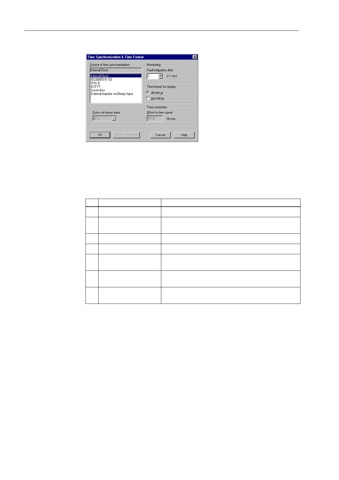
Figure 4-28 Time Synchronization & Time Format dialog box in DIGSI − Example
Specify here the factors for influencing the internal clock management. You can
choose between the following operating modes:
Due to the internal buffer battery the RTC continues to run even when the auxiliary
voltage is switched off temporarily. RTC is always the first synchronization source for
the internal clock management when the device is switched on or after a failure of the
auxiliary voltage regardless of the set operating mode.
In the operating mode Internal Clock the internal clock management uses only
RTC as the synchronization source. It can also be changed manually. The manual set-
ting of date and time is described in Chapter 6.3.7, page 231.
If one of the external operating modes is selected, only the parameterized synchroni-
zation source will be used. If it fails, the internal clock will continue in unsynchronized
mode.
If the time synchronization is to be accomplished via the control center, the option
IEC 60870-5-103 or NTP (IEC 61850) must be selected (Figure 4-28, page 76).
For the operating modes with time signal (radio clock) you must observe that it may
take up to 3 minutes after the start or return of the reception until the received time has
been safely decoded. Only then will the internal clock management be synchronized.
Table 4-1 Operating modes of the clock management
No. Operating mode Comments
1 Internal Clock Internal synchronization via RTC (default)
2 IEC 60870-5-103 External synchronization via IEC 60870-5-103−system in-
terface
3 Time signal IRIG B External synchronization via IRIG B
4 Time signal DCF77 External synchronization via the time signal DCF77
5 Time signal Sync.
Box
External synchronization via the time signal SIMEAS-
Synch.Box
6 External Impulse
via Binary Input
External synchronization with impulse via binary input
7 NTP (IEC 61850) External synchronization via system interface
(IEC 61850)

 Loading...


