INSTALLATION CHECKLIST
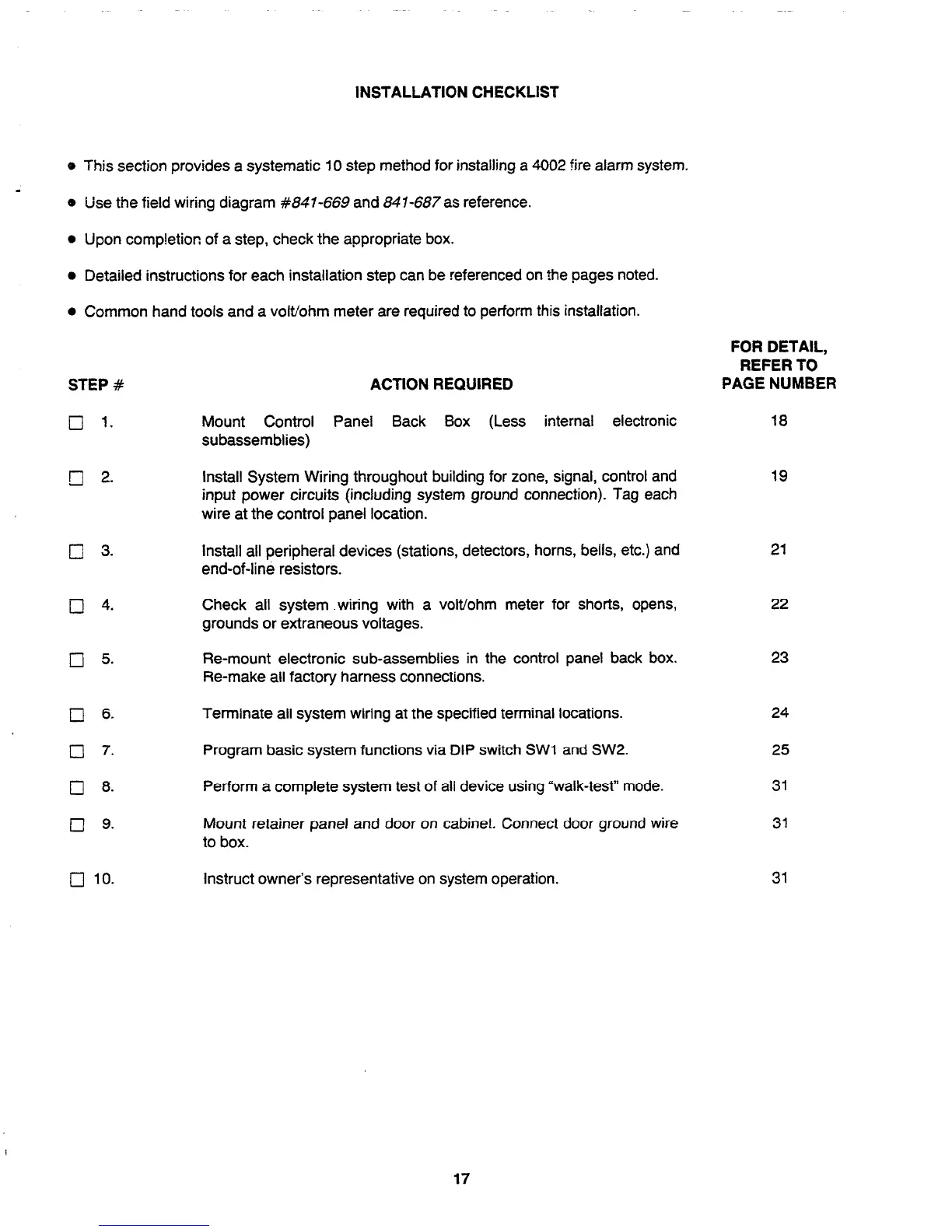
o This section provides a systematic 10 step method for installing a 4002 fire alarm system.
4
e Use the field wiring diagram
#Ml-669
and 841-687as reference.
l
Upon comp!etion of a step, check the appropriate box.
l
Detailed instructions for each installation step can be referenced on the pages noted.
l
Common hand tools and a volt/ohm meter are required to perform this installation.
STEP #
ACTION REQUIRED
q 1.
Mount Control Panel Back Box (Less internal electronic
subassemblies)
Install System Wiring throughout building for zone, signal, control and
input power circuits (including system ground connection). Tag each
wire at the control panel location.
cl 3.
install all peripheral devices (stations, detectors, horns, bells, etc.) and
end-of-line resistors.
0 4.
Check all system .wiring with a volt/ohm meter for shorts, opens,
grounds or extraneous voltages.
cl 5.
Re-mount electronic sub-assemblies in the control panel back box.
Re-make all factory harness connections.
cl
6.
Terminate all system wiring at the specified terminal locations.
Cl 7.
Program basic system functions via DIP switch SW1 and SW2.
Cl
8.
Perform a complete system test of all device using “walk-test” mode.
Cl 9.
Mount retainer panel and door on cabinet. Connect door ground wire
to box.
q
10.
Instruct owner’s representative on system operation.
FOR DETAIL,
REFER TO
PAGE NUMBER
18
19
21
22
23
24
25
31
31
31
17
Technical Manuals Online! - http://www.tech-man.com