l
incoming Power (See W.D. #841-669, [sheet 22 for 120 VAC; sheets 36,37 and 38 for 220/240 VAC]
Source: Dedicated fire alarm power circuit with a 10 amp fused disconnect or as required by local codes.
Wiring: Use two 14 AWG wires or 14 AWG cable.
l
Earth Detection
(Ground) (See W.D. #841-669)
Source: Connection must be made to an approved dedicated earth ground per NEC Article 250 (NFPA 70).
IMPORTANT
Terminate ground wire on green ground lug screw inside fire control back box.
STEP #3
MOUNTING AND WIRING PERIPHERAL DEVICES
(Refer to Wiring Diagrams 841-687 and
Instructions Provided with Each Device.)
l
Style B
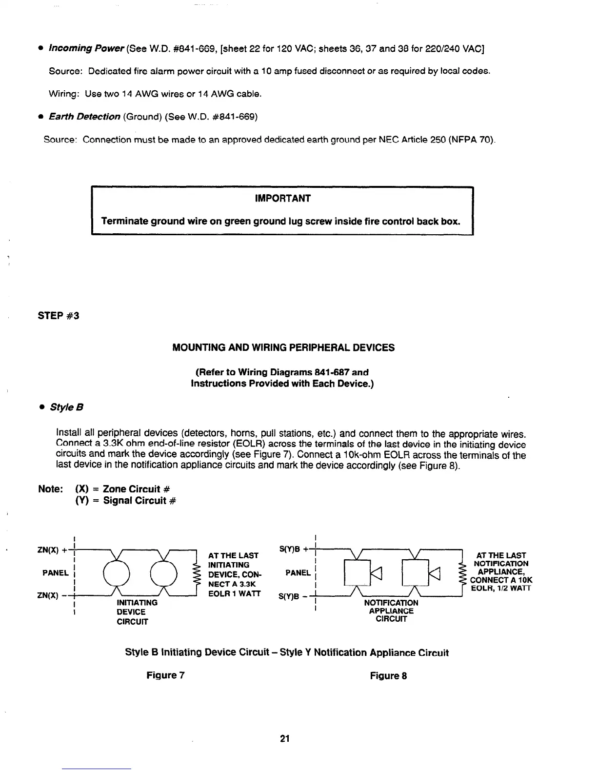
install all peripheral devices (detectors, horns, pull stations, etc.) and connect them to the appropriate wires.
Connect a 3.3K ohm end-of-line resistor (EOLR) across the terminals of the last device in the initiating device
circuits and mark the device accordingly (see Figure 7). Connect a lOk-ohm EOLR across the terminals of the
last device in the notification appliance circuits and mark the device accordingly (see Figure 8).
Note: (X) = Zone Circuit #
(Y)
= Signal Circuit #
I
DEVICE
CIRCUIT
PANEL
! L-M-k4
NOllFlCAllON
APPLIANCE
ClFlCUlT
AT THE LAST
NOTlFlCATlON
APPLIANCE,
CONNECT A 10K
EOLR, l/2 WA-IT
Style B Initiating Device Circuit - Style Y Notification Appliance Circuit
Figure 7
Figure 8
21
Technical Manuals Online! - http://www.tech-man.com