STEP #l
BACK BOX INSTALLATION
4002 Back Boxes may be shipped with or without their electronic components, and come in three different sizes.
The procedures listed below should be used when installing a back box with electronic components. Details for
mounting a back box without electronic components are shipped with the empty back boxes.
A. Systems With Electronic Components
Note:
1.
2.
3.
4.
5.
6.
7.
8.
Carefully open the shipping container.
Inventory the contents of the shipping container
to ensure complete shipment of the required
materials. (See packing list.)
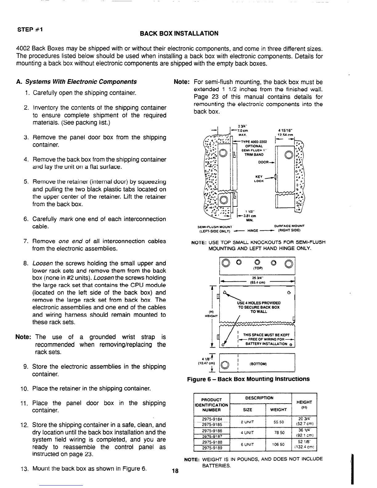
For semi-fiush mounting, the back box must be
extended 1 l/2 inches from the finished wall.
Page 23 of this manual contains details for
remounting the electronic components into the
back box.
Remove the panel door box from the shipping
container.
‘TYPE 4002-2202
OPTIONAL
SEMI-FLUSH 1”
TRIM BAND
Remove the back box from the shipping container
and lay the unit on a flat surface.
Remove the retainer (internal door) by squeezing
and pulling the two black plastic tabs located on
the upper center of the retainer. Lift the retainer
from the back box.
Carefully mark one end of each interconnection
cable.
SEMI-FLU% MOUNT
SURFACE MOUNT
(LEFT-SIDE ONLY) - HINGE -
IRIGHT SIDE)
Remove
one end
of all interconnection cables
NOTE: USE TOP SMALL KNOCKOUTS FOR SEMI-FLUSH
from the electronic assemblies.
MOUNTING AND LEFT HAND HINGE ONLY.
Loosen the screws holding the small upper and
lower rack sets and remove them from the back
box (none in #2 units). Loosen the screws holding
the large rack set that contains the CPU module
(located on the left side of the back box) and
remove the large rack set from back box. The
electronic assemblies and one end of the cables
and wiring harness should remain mounted to
these rack sets.
Note: The use of a grounded wrist strap is
9.
10.
11.
12.
13.
recommended when removing/replacing the
rack sets.
Store the electronic assemblies in the shipping
container.
Place the retainer in the shipping container.
Place the panel door box in the shipping
container.
Store the shipping container in a safe, clean, and
dry location until the back box installation and the
system field wiring is completed, and you are
ready to reassemble the control panel as
instructed on page 23.
Mount the back box as shown in Figure 6.
Figure 6 - Back Box Mounting Instructions
PRODUCT
IDENTIFICATION
NUMBER
DESCRIPTION
. HEIGHT
SIZE
WEIGHT
W)
NOTE: WEIGHT IS IN POUNDS, AND DOES NOT INCLUDE
BATTERIES.
18
Technical Manuals Online! - http://www.tech-man.com