STEP #I2 cont.
Notification Appliance Wiring
(Signal Circuits) Use Field Wiring Diagrams #841-687 and 841-669.
Examples: Horns, bells, visual units, etc.
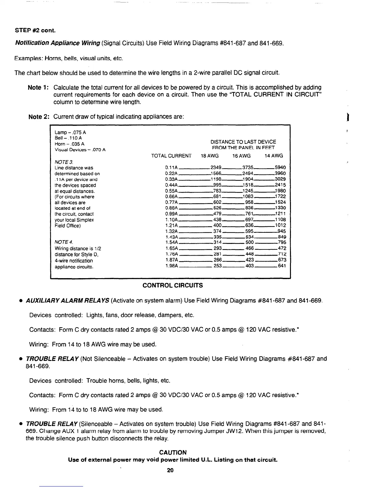
The chart below should be used to determine the wire lengths in a 2-wire parallel DC signal circuit.
Note 1: Calculate the total current for all devices to be powered by a circuit. This is accomplished by adding
current requirements for each device on a circuit. Then use the “TOTAL CURRENT IN CIRCUIT”
column to determine wire length.
Note 2: Current draw of typical indicating appliances are:
Lamp - .075 A
Bell-.llOA
Horn - ,035 A
Visual Devices - .070 A
NOTE 3.
Line distance was
determined based on
.11 A per device and
the devices spaced
at equal distances.
(For circuits where
all devices are
located at end of
the circuit, contact
your local Simplex
Field Office)
NOTE 4.
Wiring distance is l/2
distance for Style 0,
4-wire notification
appliance circuits.
DISTANCE TO LAST DEVICE
FROM THE PANEL IN FEET
TOTAL CURRENT 18 AWG
16AWG
14 AWG
O.llA 2349- 3735- 5940
0.22A 1566- 2494 -3960
0.33A 1198 -1904- 3029
0.44AA95-
1518- 241 5
0.55A 783 -1245
1980
0.66A 681 -1083
-1722
0.77A
602 958
-1524
0.88A
526 836
-1330
0.99A
479 761
1211
l.lOA 438- 697-
1108
1.21A 400 636-
1012
1.32A
374 595 945
1.43A
335 534
849
1.54A 314-
500
795
1.65A 293-
466
472
1.76A 281 448
7l?
1.87A
266 423 673
1.98A 253 403
641
CONTROL CIRCUITS
l
AUXlLIARY ALARM RELA
YS (Activate on system alarm) Use Field Wiring Diagrams #841-687 and 841-669.
Devices controlled: Lights, fans, door release, dampers, etc.
Contacts: Form C dry contacts rated 2 amps @ 30 VDC/30 VAC or 0.5 amps @ 120 VAC resistive.’
Wiring: From 14 to 18 AWG wire may be used.
0 TROUBLE RELAY
(Not Silenceable
- Activates on system trouble) Use Field Wiring Diagrams #841-687 and
841-669.
Devices controlled: Trouble horns, bells, lights, etc.
Contacts: Form C dry contacts rated 2 amps @ 30 VDC/30 VAC or 0.5 amps @ 120 VAC resistive.*
Wiring: From 14 to to 18 AWG wire may be used.
l
TROUBLE RELAY
(Silenceable - Activates on system trouble) Use Field Wiring Diagrams #841-687 and 841-
669. Change AUX
1
alarm relay from alarm to trouble by removing Jumper JW12. When this jumper is removed,
the trouble silence push button disconnects the relay.
CAUTION
Use of external power may void power limited U.L. Listing on that circuit.
20
Technical Manuals Online! - http://www.tech-man.com