APPENDIX B
FAN CONTROL MODULE (Figures 12 and 13)
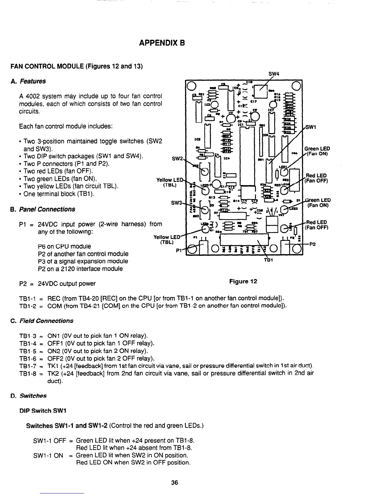
A. Features
A 4002 system may include up to four fan control
MOdUieS, each of which consists of two fan control
circuits.
Each fan control Module includes:
l
Two 3-position Maintained toggle switches (SW2
and SW3).
l
Two DIP switch packages (SW1 and SW4).
l
Two P connectors (Pl and P2).
l
Two red LEDs (fan OFF).
l
Two green LEDs (fan ON).
l
Two yellow LEDs (fan circuit TBL).
l
One terminal block (TBl).
SW2
Yebl&ED
sw3.
6. Panel Connections
Pl = 24VDC input power (2-wire harness) from
any of the following:
Yellow LED”
P6 on CPU Module
(TBL)
P2 of another fan control Module
Pl’
P3 of a signal expansion module
P2 on a 2120 interface MOdUle
P2 =
24VDC output power
Figure 12
hen LED
(Fan ON)
Red LED
:Fan OFF)
&s! LED
[Fan OFF)
-P2
r‘s1
TBl-1 =
REC (from TB4-20 [REC] on the CPU [or from TBl-1 on another fan control Module]).
TBl-2 = COM (from TB4-21 [COM] on the CPU [or from TBl-2 on another fan control Module]).
C. Field Connections
TBl-3 =
ON1 (OV out to pick fan 1 ON relay).
TBl-4 =
OFF1 (OV out to pick fan 1 OFF relay).
TBl-5 =
ON2 (OV out to pick fan 2 ON relay).
TBl-6 = OFF2 (OV out to pick fan 2 OFF relay).
TBl-7 z TK 1 (+24 [feedback] from 1 st fan circuit via vane, sail or pressure differential switch in 1 st air duct).
TBl-8 = TK2 (+24 [feedback] from 2nd fan circuit via vane, sail or pressure differential switch in 2nd air
duct).
D. Switches
DIP
Switch SW1
Switches SWl-1 and SWl-2 (Control the red and green LEDs.)
SWl-1 OFF = Green LED lit when +24 present on TBl-8.
Red LED lit when +24 absent from TBl-8.
SWl-1 ON
= Green LED lit when SW2 in ON position.
Red LED ON when SW2 in OFF position.
36
Technical Manuals Online! - http://www.tech-man.com