h. 2120 Connections
l
Transponder.
23 N/A
. interface Module (set DIP switch SW1 -8 OFF)
28
N/A
i. SCUIRCU Wiring (See Note 3)
27 NiA
j. Fan Control Module (See Note 3)
31
N/A
Notes:
1. Wire devices according to Field Wiring Diagrams 841-687.
2. If the system continues to display trouble, follow the troubleshooting procedures on page 12.
3. DIP Switch SW3 on the CPU module must be set in accordance with Table 2 on page 26. A wire
length chart is found on page 40.
STEP #7
SETTING PROGRAM DIP SWITCH SWl, SW2, AND SW3
DIP Switch, SW1 and SW2 are used to select a variety of functions which are required for alarm operations. The
locations of these switches are shown on Figure 4, page 15, or Field Wiring Diagrams 841-669, sheet 2.
Information on all basic programmable functions can be found on pages 25 through 30.
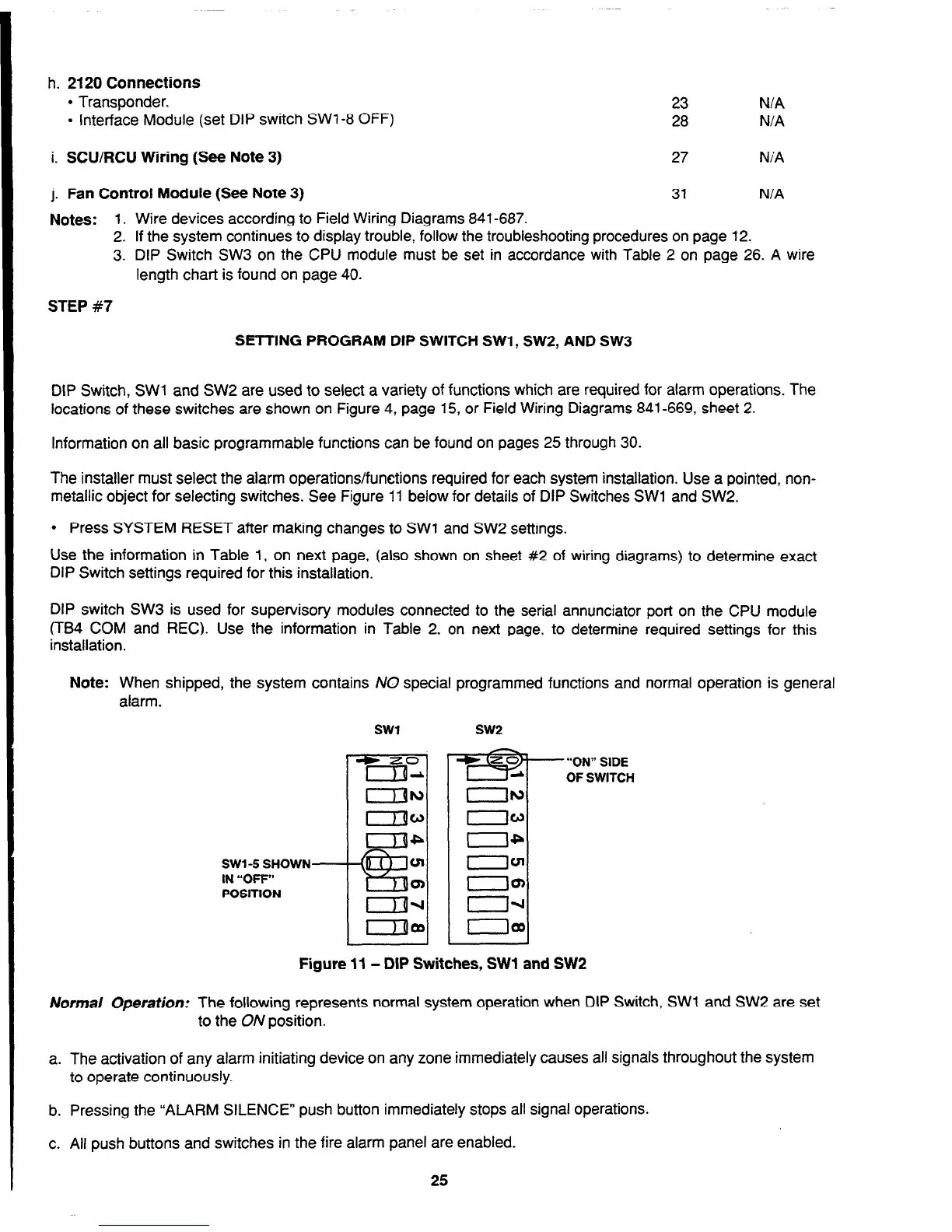
The installer must select the alarm operations/functions required for each system installation. Use a pointed, non-
metallic object for selecting switches. See Figure 11 below for details of DIP Switches SW1 and SW2.
l
Press SYSTEM RESET after making changes to SW1 and SW2 settings.
Use the information in Table 1, on next page, (also shown on sheet #2 of wiring diagrams) to determine exact
DIP Switch settings required for this installation.
DIP switch SW3 is used for supervisory modules connected to the serial annunciator port on the CPU module
(TB4 COM and REC). Use the information in Table 2, on next page, to determine required settings for this
installation.
Note: When shipped, the system contains NO special programmed functions and normal operation is general
alarm.
SW14 SHOWN-
IN “OFF”
POSITION
Figure 11 - DIP Switches, SW1 and SW2
Normal Operation: The following represents normal system operation when DIP Switch, SW1 and SW2 are set
to the ON position.
a. The activation of any alarm initiating device on any zone immediately causes all signals throughout the system
to operate continuously.
b. Pressing the “ALARM SILENCE” push button immediately stops all signal operations.
c. All push buttons and switches in the fire alarm panel are enabled.
25
Technical Manuals Online! - http://www.tech-man.com