Switch SW3
(Position determines the presence or absence of OV on terminals TBl-5 and TBl-6)
Up position
= Applies OV to TBl -5 (ON2), energizing fan control relay K3.
Center position =
Presence or absence of OV determined by the fan control module’s microprocessor.
Down position
= Applies OV to TBl-6 (OFF2), energizing fan control relay K4.
Note:
Relays K3 and K4 must mount within 3 ft. of 2nd fan motor.
DIP Switch SW4
(Allows for supervision of a fan control relay’s wiring during the relay’s de-energized state.)
SW4-1 = OFF to supervise wiring to ON1 fan control relay.
ON if circuit lacks ON1 fan control relay (or if
supervision not wanted).
SW4-2 = OFF to supervise wiring to OFF1 fan control relay.
ON if circuit lacks OFF1 fan control relay (or if
supervision not wanted).
SW4-3 = OFF to supervise wiring to ON2 fan control relay.
ON-if circuit lacks ON2 fan control relay (or if
supervision not wanted).
sw4-4 = OFF to supervise wiring to OFF2 fan control relay.
ON if circuit lacks OFF2 fan control relay (or if
supervision not wanted).
Layout,
Switch SW4
OFF
l-FN
2cn
3l
4m
Note:
If an SW4 switch is turned OFF, the appropriate TBL (yellow) LED on the fan control module
illuminates
- and the 4002 panel indicates trouble
- when an open exists in the fan control relay
circuit.
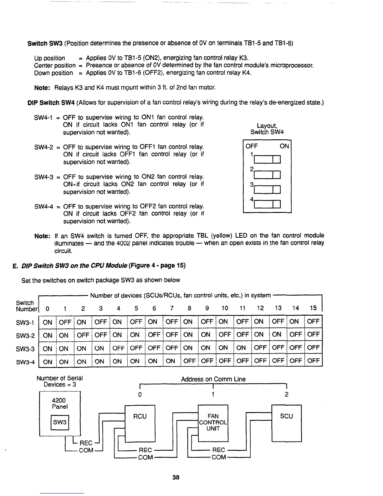
E. DIP Switch SW3 on the CPU Module (Figure 4 - page 15)
Set the switches on switch package SW3 as shown below
Switch Number/
Number of devices (SCUs/RCUs, fan control units, etc.) in system
3 4
5
6 7 8 9
10 11 12 ,131
sw3-1
SW3-2
sw3-3
sw3-4
ON /OFF/ON IOFFION
IOFFION (OFFION
IOFF~ON /OFFION /OFF/ON IOFF
ON /ON /OFF/OFF\ON /ON ~OFF(OFF/ON ION JoFF/OFF(ON (ON /OFFjCFFj
ON /ON ION ON
OFF I OFF / OFF OFF ON
ON ON ON OFF OFF OFF OFF
I
ON / ON ON ON ON ON / ON
ON
OFF OFF OFF OFF OFF OFF OFF / OFF
Number of Serial
Devices = 3
4200
Panel
cl
SW3
---/-%EC -
A
-COM-
Address on Comm Line
0
I
I
1
2
I
1
I I
RCU
38
Technical Manuals Online! - http://www.tech-man.com