STEP #I6
TERMINATIONS OF SYSTEM WIRING
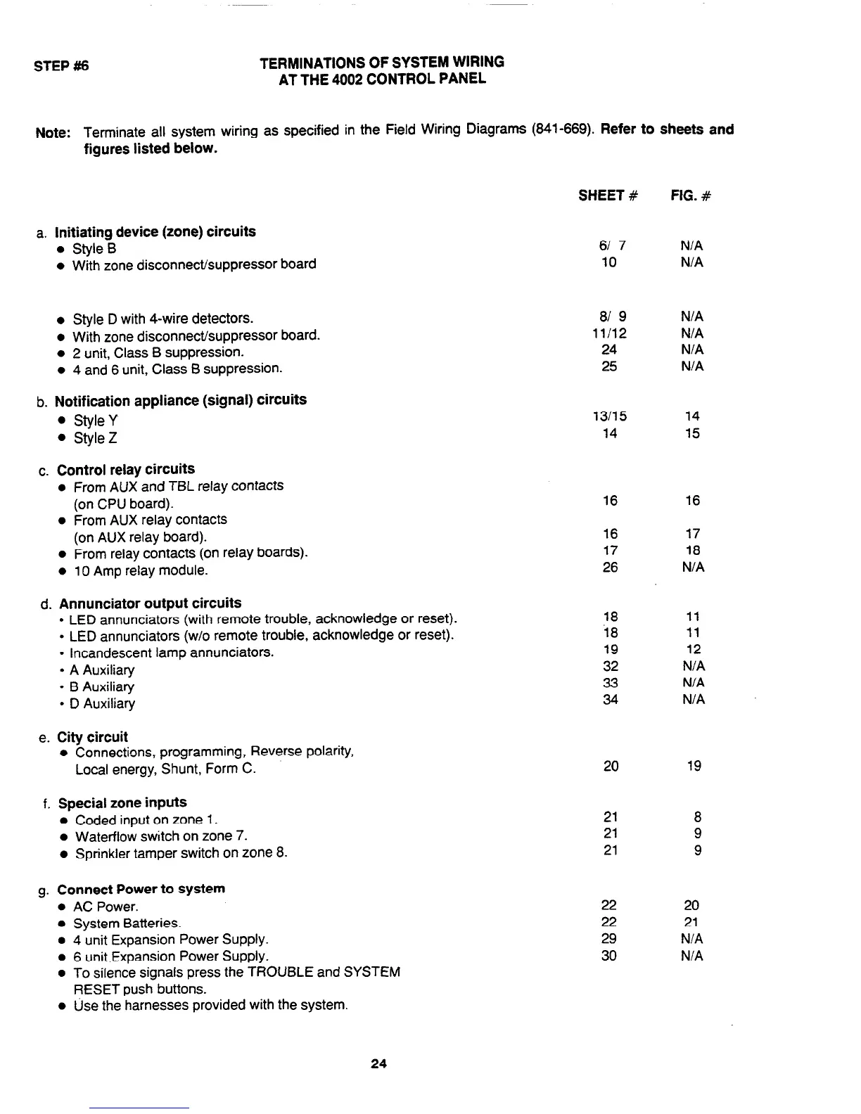
AT THE 4002 CONTROL PANEL
Note: Terminate all system wiring as specified in the Field Wiring Diagrams (641-669). Refer to sheets and
figures listed below.
a. Initiating device (zone) circuits
l
Style B
l
With zone disconnect/suppressor board
l
Style D with 4-wire detectors.
81 9 N/A
l
With zone disconnect/suppressor board.
11/12
N/A
l
2 unit, Class B suppression.
24 N/A
l
4 and 6 unit, Class B suppression.
25 N/A
b. Notification appliance (signal) circuits
l
Style Y
l
Style Z
c. Control relay circuits
l
From AUX and TBL relay contacts
(on CPU board).
l
From AUX relay contacts
(on AUX relay board).
l
From relay contacts (on relay boards).
l
10 Amp relay module.
d. Annunciator output circuits
l
LED annunciators (with remote trouble, acknowledge or reset).
l
LED annunciators (w/o remote trouble, acknowledge or reset).
l
Incandescent lamp annunciators.
l
A Auxiliary
l
B Auxiliary
l
D Auxiliary
e. City circuit
l
Connections, programming, Reverse polarity,
Local energy, Shunt, Form C.
f. Special zone inputs
l
Coded input on zone 1.
l
Waterflow switch on zone 7.
l
Sprinkler tamper switch on zone 8.
g. Connect Power to system
l
AC Power.
l
System Batteries.
l
4 unit Expansion Power Supply.
l
6 unit Expansion Power Supply.
l
To silence signals press the TROUBLE and SYSTEM
RESET push buttons.
l
Use the harnesses provided with the system.
SHEET #
FIG. #
61 7 N/A
10 N/A
13115
14
16 16
16 17
17
18
26
N/A
18
11
i8
11
19 12
32 N/A
33
N/A
34
N/A
20
21
8
21
9
21
9
22
20
22
21
29
N/A
30
N/A
14
15
19
24
Technical Manuals Online! - http://www.tech-man.com